Piston pump and relative control method

a technology of piston pump and relative control method, which is applied in the direction of piston pump, positive displacement liquid engine, pump parameter, etc., can solve the problems of high pressure oscillation, the adjustment device described therein cannot be applied to the piston pump, and the user cannot adjust the flow rate and reverse the piston pump

Active Publication Date: 2021-02-09
MARELLI EURO SPA
View PDF10 Cites 2 Cited by
  • Summary
  • Abstract
  • Description
  • Claims
  • Application Information

AI Technical Summary

Benefits of technology

[0009]Therefore, the object of the invention is to provide a piston pump and a relative control method which are not affected by the drawbacks of the prior art and, at the same time, are easy and economical to be manufactured and implemented.

Problems solved by technology

However, the system described therein does not allow users to adjust the flow rate and reverse the piston pump.
However, the adjustment device described therein cannot be applied to a piston pump, since this would lead to too high pressure oscillations (“ripples”).
Therefore, to sum up, external devices for the removal of the liquid from the delivery duct are very large and difficult to be manufactured; whereas flow rate adjustment devices cannot usually be applied to piston pumps because they cause very high pressure oscillations (“ripples”).
This piston pump evidently requires a large number of elements and, therefore, is hard and expensive to be manufactured and, furthermore, turns out to be large-sized.

Method used


Image

  • Piston pump and relative control method
  • Piston pump and relative control method
  • Piston pump and relative control method

Examples


first embodiment

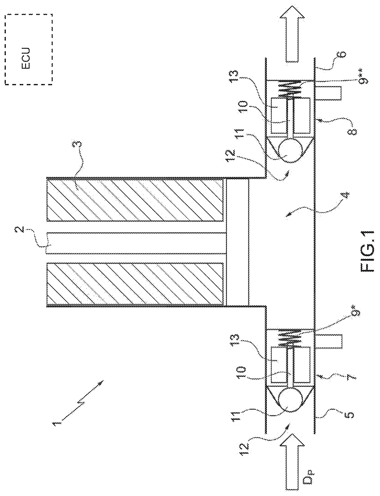
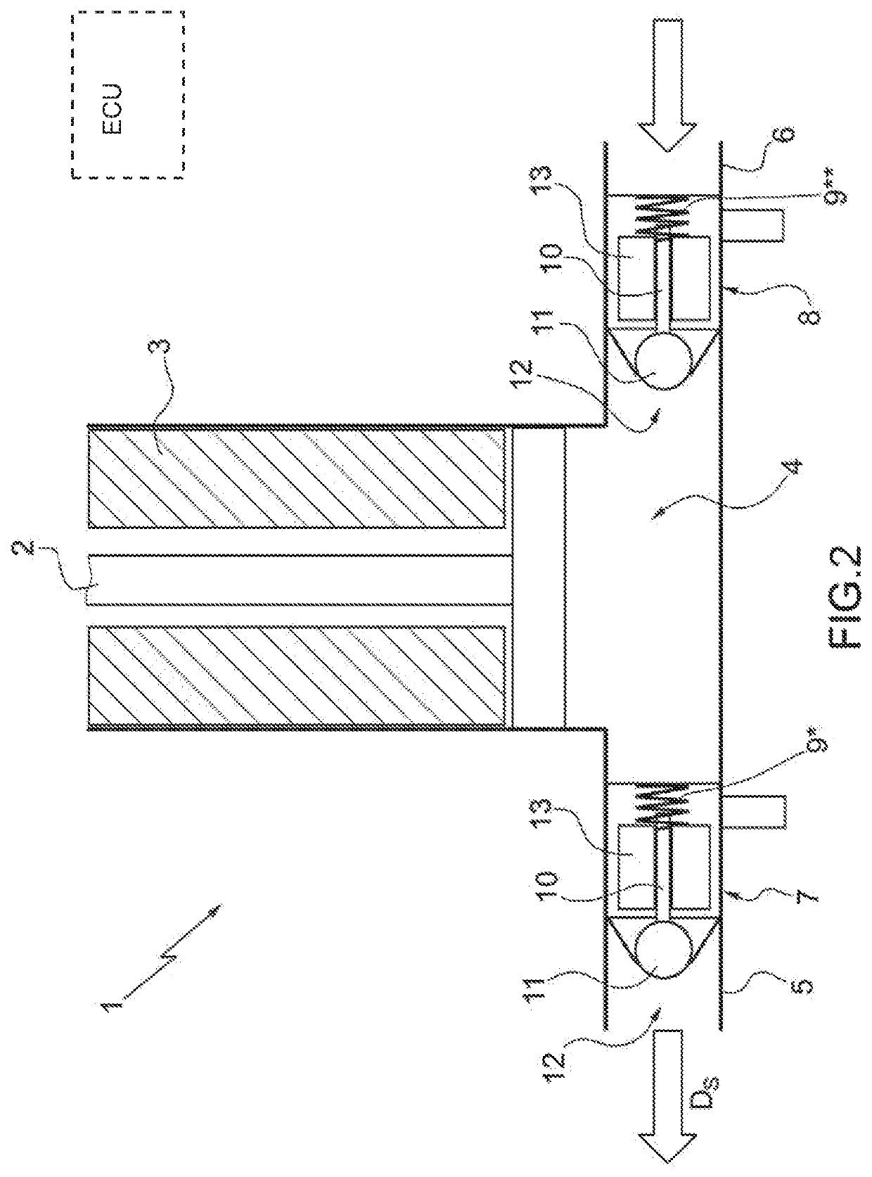
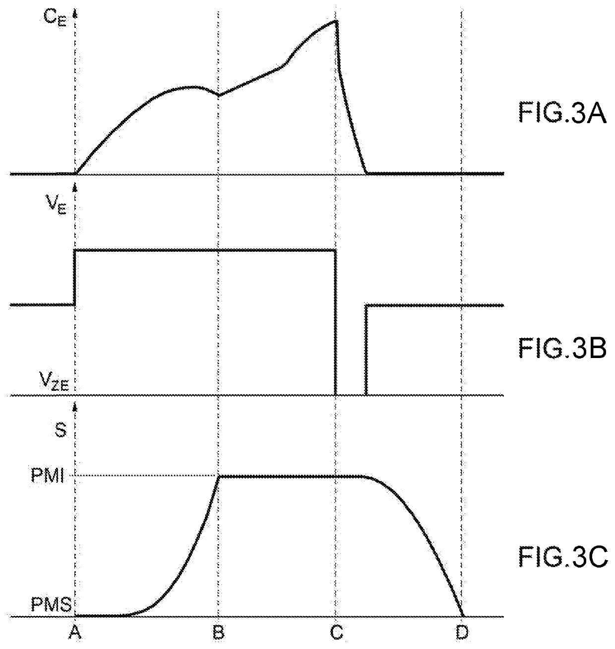
[0014]FIG. 3A relates to a first embodiment, in which the piston of the piston pump is operated by an electromagnet, and shows the time development of the current absorbed by an electromagnet operating the piston of the pump of FIGS. 1 and 2;

[0015]FIG. 3B relates to the first embodiment and shows the time development of the voltage of the electromagnet operating the piston of the pump of FIGS. 1 and 2;

[0016]FIG. 3C relates to the first embodiment and shows the time development of the movement of the piston of the pump of FIGS. 1 and 2;

[0017]FIG. 4A relates to the first embodiment and shows the time development of the power supply current of the piston pump of FIGS. 1 and 2;

[0018]FIG. 4B relates to the first embodiment and shows the time development of the power supply voltage of the piston pump of FIGS. 1 and 2;

[0019]FIG. 4C relates to the first embodiment and shows the time development of the movement of the piston of the piston pump of FIGS. 1 and 2;

[0020]FIG. 4D relates to the fi...

second embodiment

[0021]FIG. 5A relates to a second embodiment, which is not part of the invention and in which the piston of the piston pump is operated by a cam, and shows the movement of the piston as a function of the rotation angle of the cam; and

[0022]FIG. 5B relates to the second embodiment, which is not part of the invention, and shows the activation signal of the electromagnetic valves.


PUM


Abstract

A piston pump for feeding a liquid in a vehicle having at least one piston, which is configured to cyclically slide inside a housing between a top dead centre and a bottom dead centre. The liquid is usually fed along a main feeding direction from a suction duct to a delivery duct. The piston pump has two solenoid valves, which are each arranged in the suction duct and in the delivery duct, respectively, and are designed to be operated by an electronic control unit so as to reverse the liquid feeding direction from the main feeding direction to a secondary feeding direction opposite the main liquid feeding direction and / or so as to adjust the cylinder capacity of the piston pump. The piston is operated by an electromechanical actuator, in particular comprising an electromagnet.

Description

CROSS-REFERENCE TO RELATED APPLICATIONS[0001]This patent application claims priority from Italian patent application no. 102018000004099 filed on Mar. 29, 2018, the entire disclosure of which is incorporated herein by reference.BACKGROUND OF THE INVENTION1. Field of the Invention[0002]The invention relates to a piston pump and to a relative control method.2. Description of the Related Art[0003]The invention finds advantageous application in internal combustion engines, where a liquid (for example, fuel or a cooling liquid or a water-based cleaning liquid) is fed through a pump. It is well-known that a pump feeds the liquid coming from a tank to a delivery pipe, which ends in at least one using device.[0004]During the use, the need can arise to remove the liquid previously fed to the delivery pipe arranged downstream of the pump.[0005]Patent application DE102014222463A1 discloses different methods to feed liquid (in particular, water) into a delivery duct or, alternatively, remove it...

Claims


Application Information

Patent Timeline
Patent Type & Authority Patents(United States)
IPC IPC(8): F04B7/00F04B49/22F04B49/03F04B17/04
CPCF04B7/0076F04B17/044F04B49/03F04B49/22F04B2201/0201F04B2203/0401F04B17/03F04B49/06F04B53/1082F04B49/065F04B2205/05
Inventor DE CESARE, MATTEOTORCOLINI, NICOLA
Owner MARELLI EURO SPA
Why Eureka
Try Eureka