Engine assembly with vibration-isolated ignition coil apparatus

a technology of vibration isolation and ignition coil, which is applied in the direction of machines/engines, spark plugs, transformers/react mounting/support/suspension, etc., can solve the problems of electrical components, may be sensitive to engine vibration, etc., and achieve the effect of reducing movemen

Active Publication Date: 2021-02-09
GM GLOBAL TECH OPERATIONS LLC
View PDF2 Cites 1 Cited by
  • Summary
  • Abstract
  • Description
  • Claims
  • Application Information

AI Technical Summary

Benefits of technology

[0003]The elastomeric boot and the elastomeric isolator may be sufficiently resiliently deformable to dampen engine vibrations and prevent excessive vibration of the electrical connector and ignition coil apparatus. Utilizing the elastomeric boot as a vibration isolator and utilizing a single fastener for the ignition coil housing may reduce component count, reduce mass, and conform with packaging space limitations.
[0005]The single fastener and the fastener opening in the ignition coil housing may be configured such that the single fastener is able to translate relative to the ignition coil housing in the fastener opening, such as, for example, when an engine block assembly on which the elastomeric boot is mounted and to which a proximal end of the single fastener is fixed vibrates. The elastomeric boot may be supported on and the single fastener fixed to at least one of a cylinder head, a cam cover, or a rocker cover of the engine assembly. Stated differently, the single fastener is able to move relative to the ignition coil housing in the fastener opening when the engine assembly vibrates, and the isolator is able to dampen the movement.

Problems solved by technology

Electrical components, such as an electrical connector mounted to an ignition coil housing, may be sensitive to engine vibrations.

Method used


Image

  • Engine assembly with vibration-isolated ignition coil apparatus
  • Engine assembly with vibration-isolated ignition coil apparatus
  • Engine assembly with vibration-isolated ignition coil apparatus

Examples


Embodiment Construction

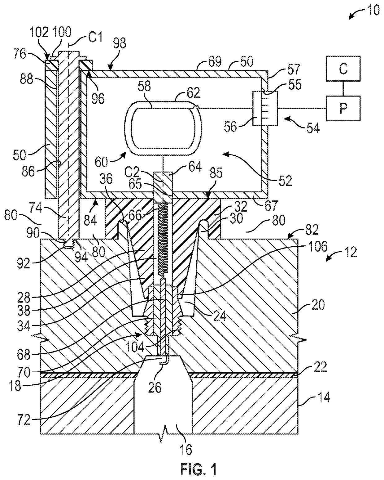
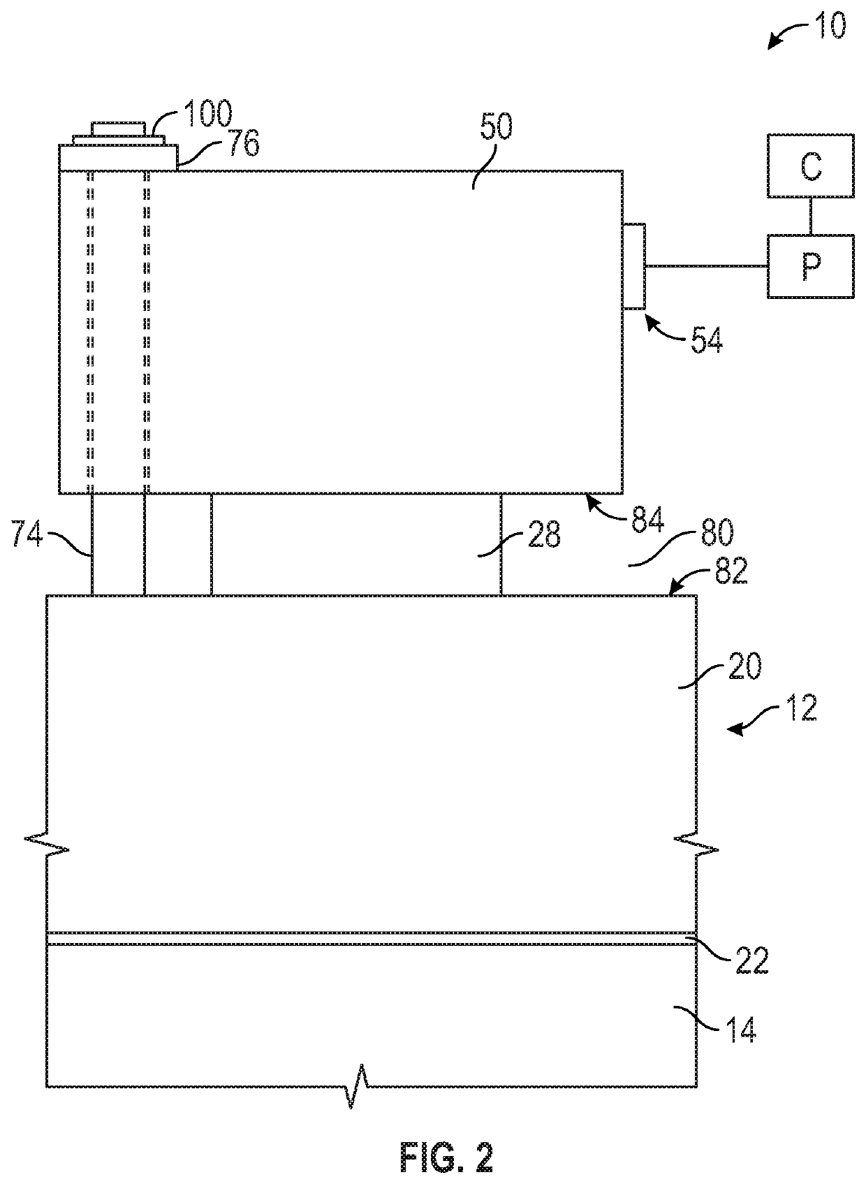
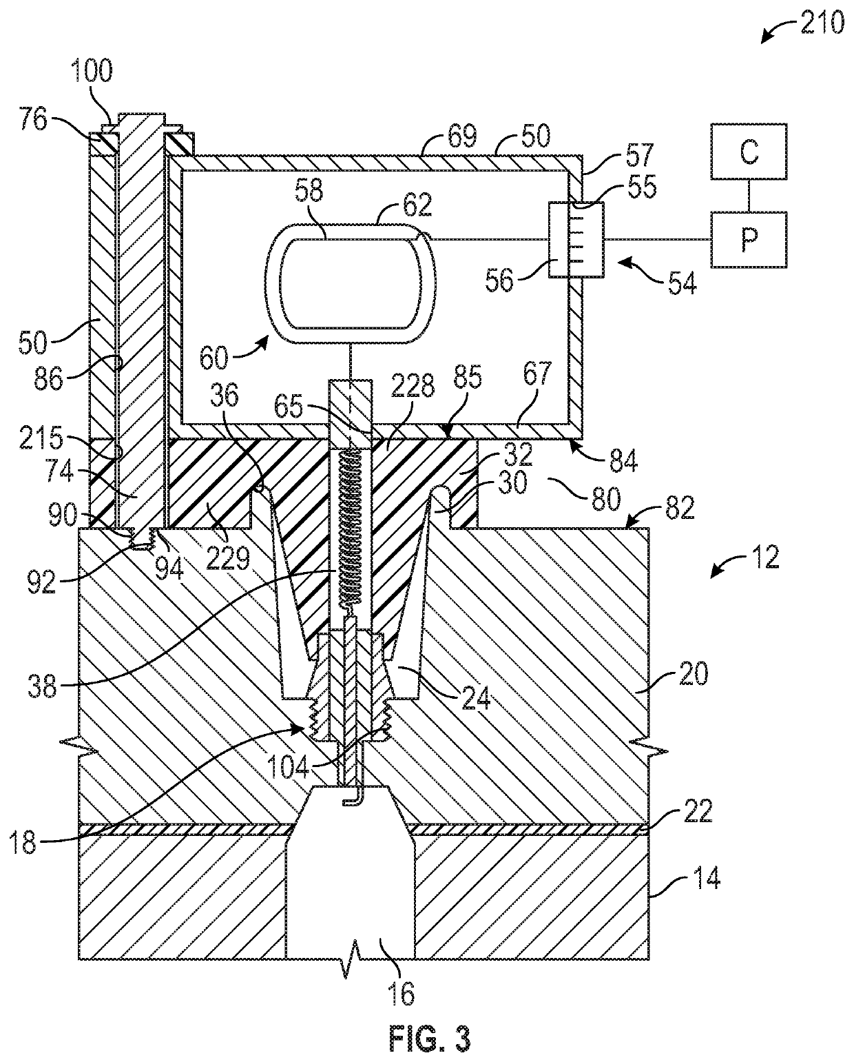
[0020]Referring to the drawings, wherein like reference numbers refer to like components, FIG. 1 shows an engine assembly such as for a vehicle, including an automotive vehicle or a nonautomotive vehicle. The vehicle may be autonomous or driven by a human, and may include, but not be limited to a mobile platform in the form of a commercial vehicle (car, truck, sport utility vehicle, etc.), industrial vehicle (bus, etc.), agricultural vehicle, passenger vehicle, aircraft, watercraft, train, all-terrain vehicle, personal movement apparatus, robot and the like to accomplish the purposes of this disclosure. Still further, the engine assembly 10 could be for a non-vehicle application.

[0021]The engine assembly 10 is a combustion engine that uses spark ignition. The engine assembly 10 includes an engine block assembly 12 that has an engine block 14 that defines combustion cylinders 16 (one shown). A spark plug 18 is supported by another engine component of the engine block assembly 12, suc...


PUM

PropertyMeasurementUnit
heightaaaaaaaaaa
poweraaaaaaaaaa
electrical poweraaaaaaaaaa

Abstract

An engine ignition coil assembly disclosed herein provides an ignition coil housing that may be mounted on an engine block assembly and that is isolated from engine vibrations. The engine ignition coil assembly comprises an ignition coil housing. The ignition coil housing contains an ignition coil apparatus. An electrical connector for the ignition coil apparatus is mounted to the ignition coil housing. An elastomeric boot supports the ignition coil housing and may be disposed on an engine block assembly such that ignition coil housing is spaced apart from the engine block assembly by the elastomeric boot. A single fastener extends through a fastener opening in the ignition coil housing parallel with the elastomeric boot. An elastomeric isolator is disposed on the ignition coil housing at the fastener opening around the single fastener. A proximal end of the single fastener may be fixed to the engine block assembly.

Description

INTRODUCTION[0001]The present disclosure relates to an engine ignition coil assembly with an ignition coil housing. On an internal combustion engine, an ignition coil housing is mounted to a component of an engine block assembly, such as a cylinder head. An electrical connector may be integrally mounted to the housing to provide electrical power from a power source to a transformer in the ignition coil housing, which powers a spark plug mounted on the engine block assembly.SUMMARY[0002]Electrical components, such as an electrical connector mounted to an ignition coil housing, may be sensitive to engine vibrations. An engine ignition coil assembly disclosed herein provides an ignition coil housing that may be mounted on an engine block assembly and that is isolated from engine vibrations. The engine ignition coil assembly comprises an ignition coil housing. The ignition coil housing contains an ignition coil apparatus. An electrical connector for the ignition coil apparatus is mounte...

Claims


Application Information

Patent Timeline
Patent Type & Authority Patents(United States)
IPC IPC(8): F02P3/00H01F38/12F02P3/055F02P13/00F02F1/24H01T13/08H01T13/04
CPCH01F38/12F02P3/055F02P13/00F02F1/242H01T13/04H01T13/08H01F27/06H01F27/28H01F27/02H01T13/44F02P3/04
Inventor KUBANI, RONALD J.BLAND, JR., COBURN C.WHITAKER, SEAN M.
Owner GM GLOBAL TECH OPERATIONS LLC
Why Eureka
Try Eureka