Lancing safety cap apparatus

a safety cap and fitting technology, applied in the direction of cleaning process and equipment, chemistry apparatus and processes, and wellbore/well accessories, etc., can solve the problems of reducing the effective inside diameter of the pipe and reducing the flow ra

Active Publication Date: 2021-02-23
TRI STATE ENVIRONMENTAL LLC
View PDF19 Cites 0 Cited by
  • Summary
  • Abstract
  • Description
  • Claims
  • Application Information

AI Technical Summary

Benefits of technology

[0007]The apparatus of the present invention is an improved safety cap fitting apparatus for enabling piping systems such as oil and gas well pipes to be cleaned onsite and that allows for the cap and lancing tools to be used in hard-to-reach places. The present invention also includes an improved method of using the safety cap fitting apparatus to clean pipes onsite and in hard-to-reach places.

Problems solved by technology

Eventually this caked on drilling mud must be removed because it reduces the effective inside diameter of the pipe, thus reducing flow rates.

Method used


Image

  • Lancing safety cap apparatus
  • Lancing safety cap apparatus
  • Lancing safety cap apparatus

Examples


Embodiment Construction

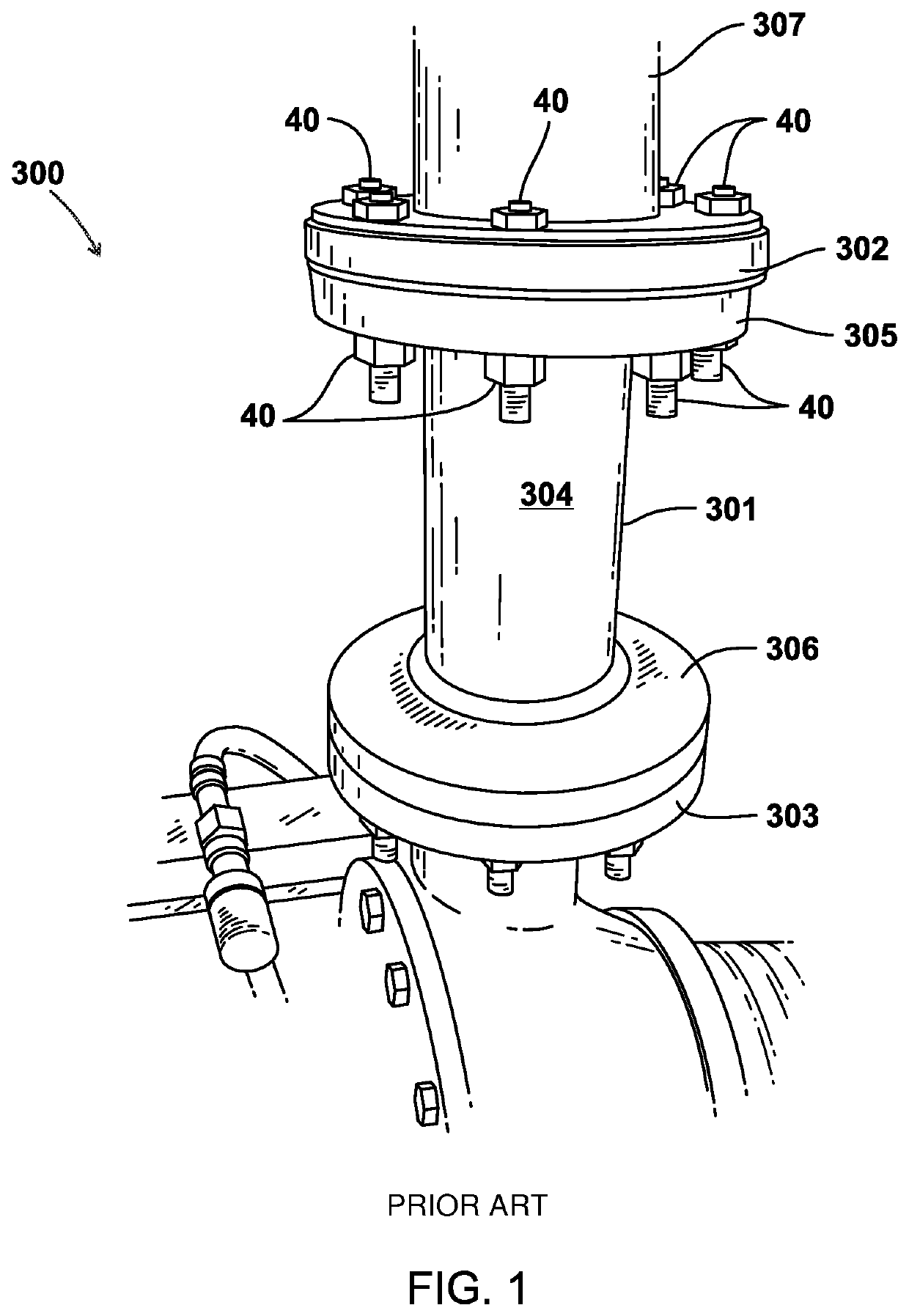
[0032]FIG. 1 shows a piping system 300 to be cleaned. Piping system 300 may have a removable piping segment or spool piece 301. Spool piece 301 can be comprised of pipe flanges 305, 306 that are welded or otherwise connected to a section 304 (or sections) of pipe or tubular material. The spool piece 301 can also include one or more fittings such as one or more elbows, tees, valves or other fitting or fittings. Spool pieces 301 are typically shop prepared (e.g., welded) and then field assembled to other spool pieces or lengths of pipe or fittings or valves or other piping components (e.g., using bolted connections 40). Such spool pieces 301 are well known in the art. Once a spool piece 301 is removed, flanges 302, 303 of piping system 300 are exposed. Piping system 300 includes piping to be cleaned such as pipe section 307. Pipe section 307 can be connected (e.g., welded) to flange 302. Adapter 21 of fitting 10 may then be attached to a selected flange 302 or 303 by bolts or bolted c...


PUM


Abstract

The present invention relates to safety caps for lancing procedures, and a method of cleaning piping systems using said safety caps. More particularly, the present invention relates to an improved safety cap for oil and gas well pipes to be cleaned onsite that allows for the cap and lancing tools to be used in hard-to-reach places.

Description

CROSS-REFERENCE TO RELATED APPLICATIONS[0001]This application claims the benefit of U.S. Provisional Patent Application No. 62 / 503,126, filed 8 May 2017; priority of U.S. Provisional Patent Application No. 62 / 503,126, filed 8 May 2017 is hereby claimed.[0002]Incorporated herein by reference are U.S. Provisional Patent Application No. 62 / 503,126, filed 8 May 2017; U.S. Provisional Patent Application No. 62 / 068,441, filed 24 Oct. 2014; U.S. Provisional Patent Application No. 62 / 164,978, filed 21 May 2015; U.S. Provisional Patent Application No. 62 / 164,985, filed 21 May 2015; U.S. Provisional Patent Application No. 62 / 191,991, filed on 13 Jul. 2015; US Provisional Patent Application No. 62 / 245,697, filed 23 Oct. 2015; U.S. Provisional Patent Application No. 62 / 329,341, filed 29 Apr. 2016; U.S. patent application Ser. No. 15 / 162,460, filed on 23 May 2016; and U.S. patent application Ser. No. 15 / 162,540, filed on 23 May 2016.STATEMENT REGARDING FEDERALLY SPONSORED RESEARCH OR DEVELOPMENT...

Claims


Application Information

Patent Timeline
Patent Type & Authority Patents(United States)
IPC IPC(8): B08B9/043E21B41/00
CPCB08B9/0433E21B41/00B08B2209/032B08B2209/04B08B9/043
Inventor CARTER, ANTHONY SCOTT
Owner TRI STATE ENVIRONMENTAL LLC
Why Eureka
Try Eureka