Wire guide assembly

a wire guide and assembly technology, applied in the field of wire guide assembly, can solve the problems of reducing reliability, requiring a large number of man-hours to assemble and clean the wire guide assembly that has a complicated shape, and reducing the connection of the hinge wir

Inactive Publication Date: 2017-07-27
FANUC LTD
View PDF0 Cites 0 Cited by
  • Summary
  • Abstract
  • Description
  • Claims
  • Application Information

AI Technical Summary

Benefits of technology

[0018]According to the present invention, there can be provided a wire guide assembly capable of cleaning w

Problems solved by technology

If the wire residue is accumulated in a wire guide assembly, it may hinder wire connection and reduce reliability.
However, it requires a large number of man-hours to assemble and clean the wire guide assembly that has a complicated shape.
In the technique disclosed in Japanese Patent-Application Laid-Open No. 2010-69541, however, it is difficult to remove once adhered wire residue due to a low fluid pressure, although the wire residue can be prevented from being accumulated.
I

Method used


Image

  • Wire guide assembly
  • Wire guide assembly
  • Wire guide assembly

Examples


Embodiment Construction

[0025]One embodiment of the present invention will now be described with reference to the accompanying drawings.

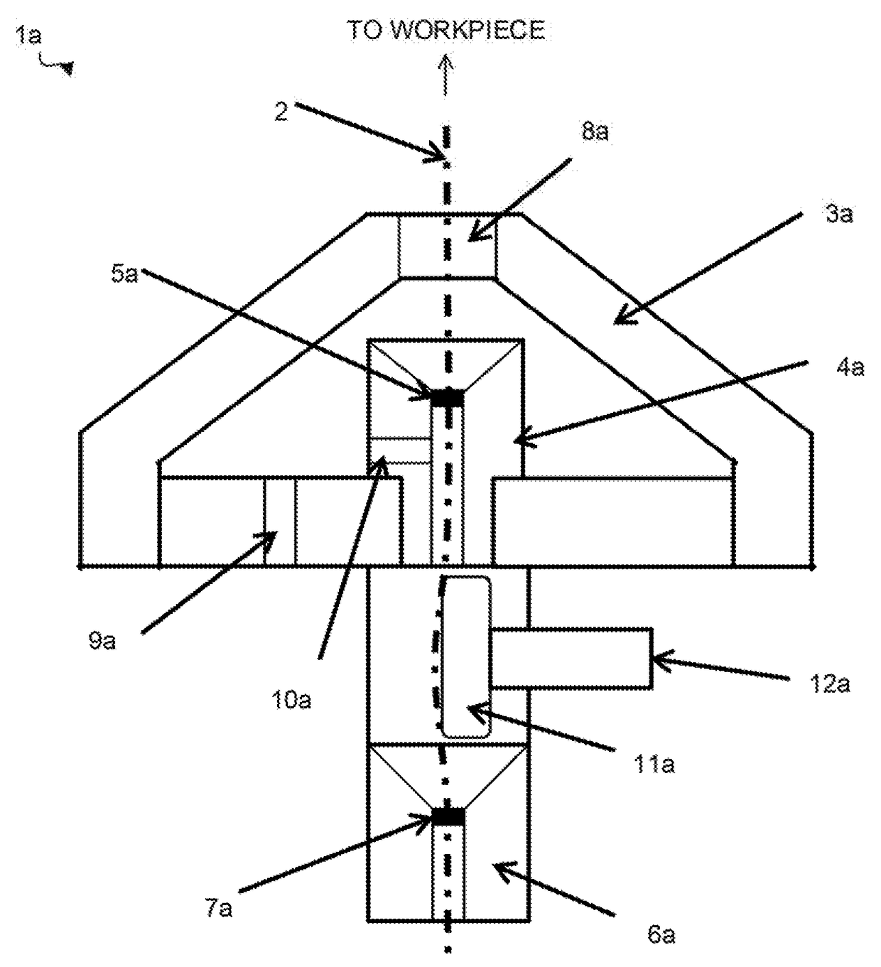
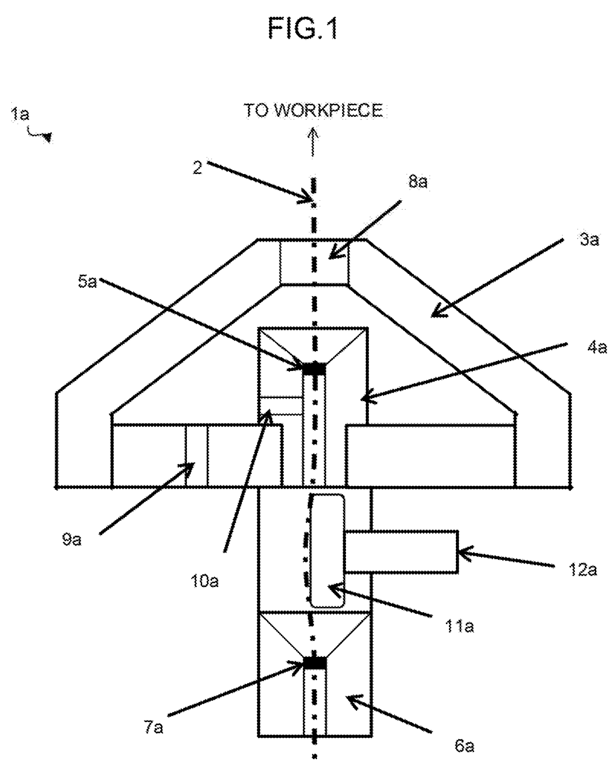
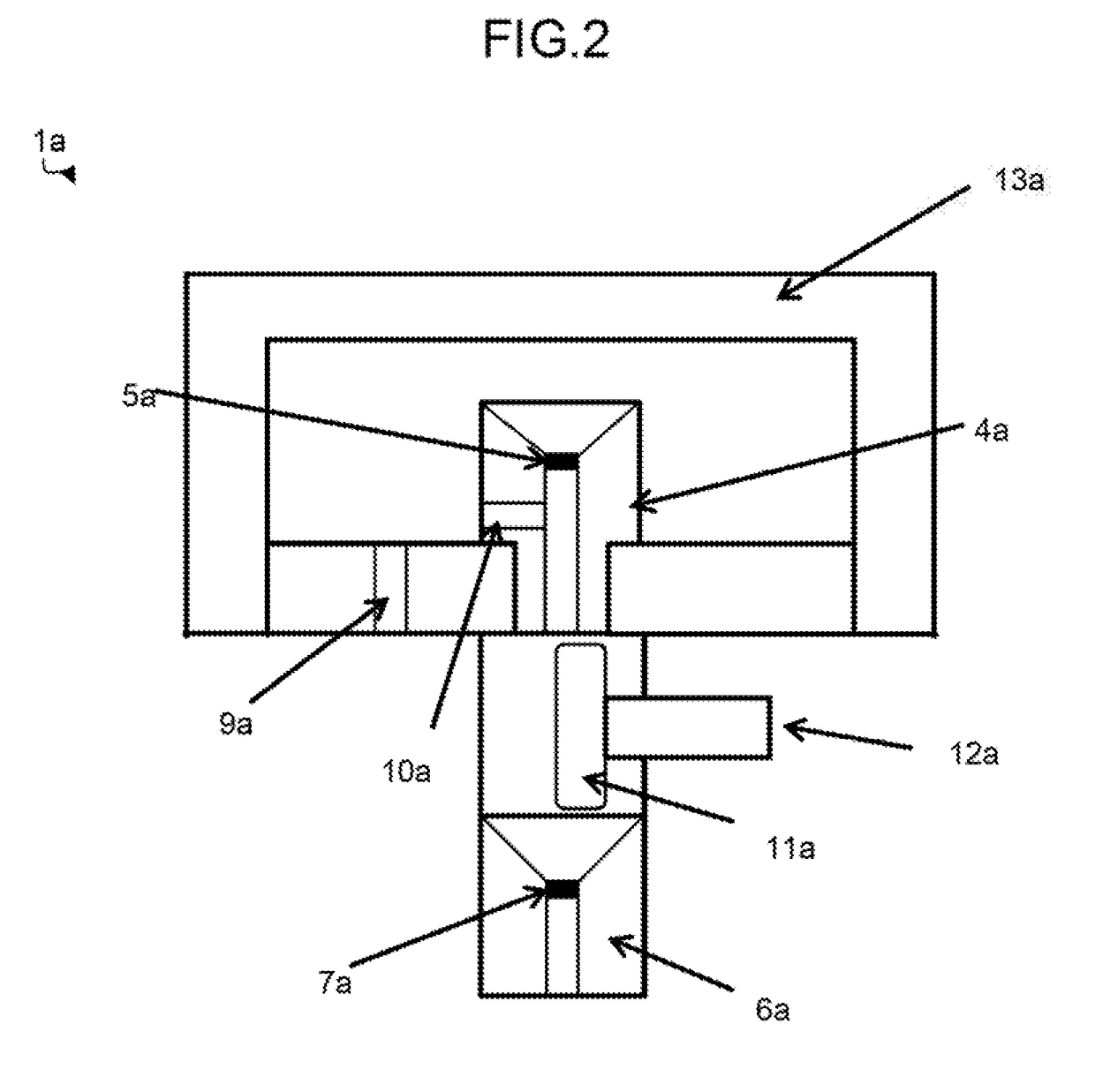
[0026]FIG. 1 is a schematic configuration diagram of a lower wire guide assembly according to the one embodiment of the present invention in a normal state. A lower wire guide assembly 1a and an upper wire guide assembly 1b (described later) are vertically arranged with a workpiece (not shown) therebetween and serve to rectilinearly guide a wire electrode 2. The lower wire guide assembly 1a of the present embodiment is constructed so that a die guide 4a is assembled to a nozzle 3a. A die hole 5a through which the wire electrode 2 is passed is provided at one end of the die guide 4a, while a sub-guide 6a with a sub-die hole 7a for guiding the traveling direction of the wire electrode 2 is secured to an opposite end portion of the die hole 5a. The wire electrode 2 is passed through a nozzle hole 8a in the nozzle 3a, the die hole 5a, and the sub-die hole 7a as it is guided.

[0...


PUM

PropertyMeasurementUnit
Pressureaaaaaaaaaa
Flow rateaaaaaaaaaa

Abstract

A wire guide assembly of the present invention is provided with a working fluid inlet port through which a working fluid flows info the wire guide assembly and a nozzle with a working fluid outlet port which is attached to the wire guide assembly at least during machining and through which the working fluid is allowed to flow out from the wire guide assembly. The working fluid is prevented from flowing out from the wire guide assembly while the interior of the wire guide assembly is being cleaned, thereby enabling cleaning with a high-pressure flow of the working fluid produced in the wire guide assembly.

Description

BACKGROUND OF THE INVENTION[0001]Field of the Invention[0002]The present invention relates to a wire guide assembly, and more particularly, to a wire guide assembly that uses a closed nozzle at the time of cleaning.[0003]Description of the Related Art[0004]When a wire electrode is fed out, wire residue is produced as it rubs against ail electrode pin or a wire guide. If the wire residue is accumulated in a wire guide assembly, it may hinder wire connection and reduce reliability. Moreover, if the wire residue adheres to the wire guide, the traveling direction of the wire is inclined, so that the machining accuracy is reduced or breakage is induced. Therefore, it is necessary to disassemble and clean the wire guide assembly periodically. However, it requires a large number of man-hours to assemble and clean the wire guide assembly that has a complicated shape. Furthermore, adjustment work such as vertical feed must be tried again, so that the machining accuracy may be reduced by an o...

Claims


Application Information

Patent Timeline
IPC IPC(8): B23H7/10B23H7/26
CPCB23H7/26B23H7/105B23H7/101B23H7/36B23H1/10B23H11/00
Inventor HADA, KEITA
Owner FANUC LTD
Why Eureka
Try Eureka