3D printer with multiple light sources and its controlling method

a 3d printer and light source technology, applied in the field of 3d printers, can solve the problems of reducing the resolution of the image, limited print area and printing precision, and the 3d printer has several drawbacks, and achieves the effect of high speed and precision, and large printing area

Active Publication Date: 2021-02-23
SHAOXING FAST REAL ELECTRONICS TECH CO LTD
View PDF7 Cites 0 Cited by
  • Summary
  • Abstract
  • Description
  • Claims
  • Application Information

AI Technical Summary

Benefits of technology

[0007]According to the present invention, a DLP 3D printer is described. The DLP 3D printer incorporates with multiple light sources for creating a large printing area in a high speed and precision manner.
[0010]It is further another object of the present invention to provide a DLP 3D printer, which permits the user to quickly and easily built a bigger 3D object in timely and precise manner.
[0011]It is further another object of the present invention to provide a DLP 3D printer, wherein the voxels of each discrete image are corrected its distortion to enhance the printing quality of the 3D object.
[0012]It is yet another object of the present invention to provide a DLP 3D printer, wherein the light sources are immovable during the operation to minimize the vibration of each of the light sources.
[0014]It is yet another object of the present invention to provide a DLP 3D printer, which is easy to use without assistance, and inexpensive to manufacture.
[0015]It is yet another object of the present invention to provide a DLP 3D printer, wherein the control method thereof is simply and effective to build a bigger 3D object while being time effective.

Problems solved by technology

However, the conventional DLP 3D printer has several drawbacks.
Therefore, the print area and the precision of printing are limited by the resolution of the single image and the numbers of voxels.
However, the resolution of the image will be decreased.
Thus, the movement of the digital projector will create vibration to affect the precision of the printing.
The printing quality of the 3D object will be affected not only by the resolution of the image but also by the distortion of the voxel.

Method used


Image

  • 3D printer with multiple light sources and its controlling method
  • 3D printer with multiple light sources and its controlling method
  • 3D printer with multiple light sources and its controlling method

Examples


Embodiment Construction

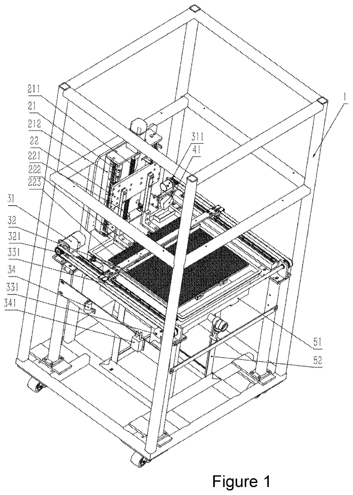
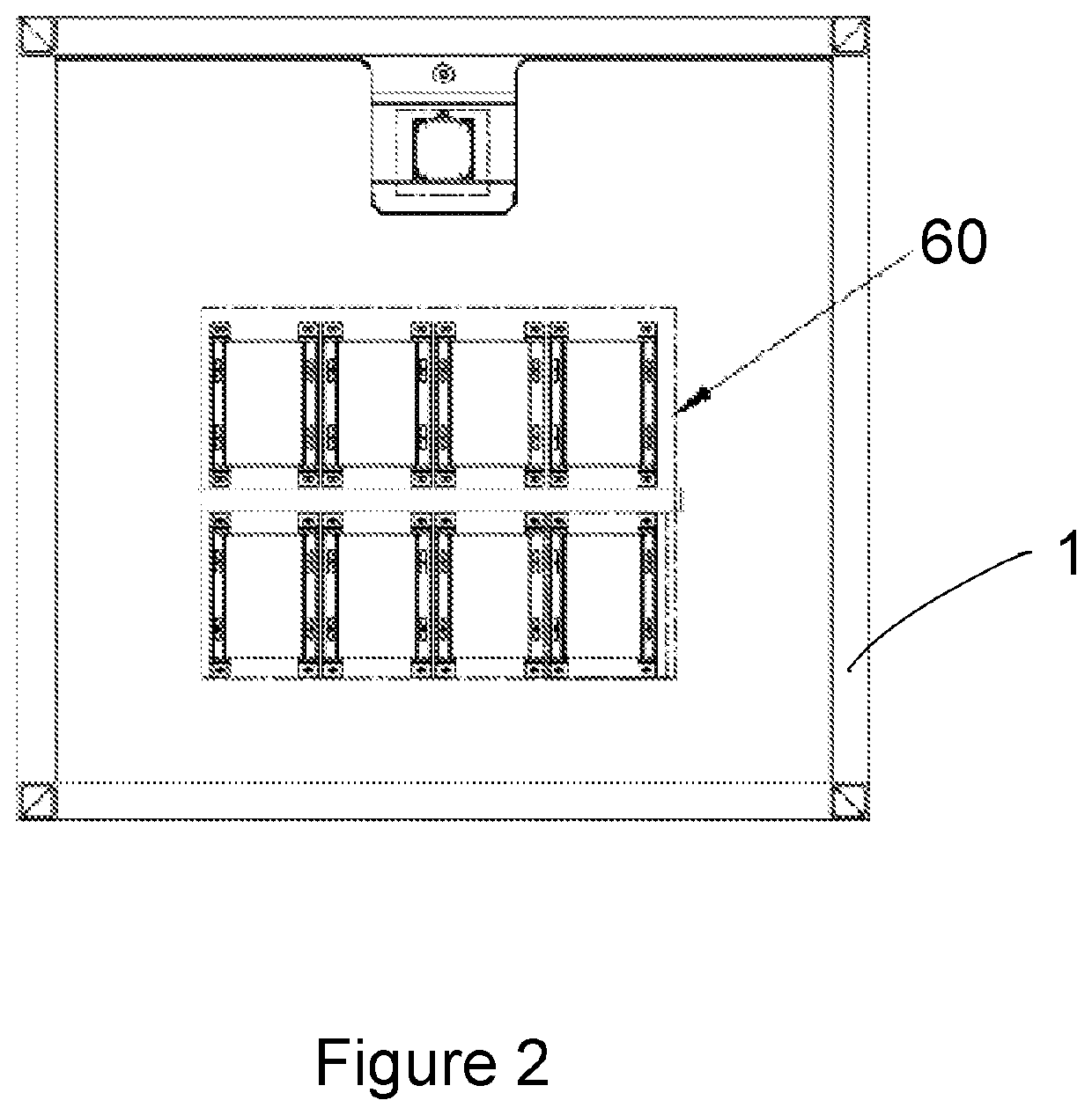
[0028]For purposes of description herein the terms “upper,”“lower,”“right,”“left,”“rear,”“front,”“vertical,”“horizontal” and derivatives thereof shall relate to the invention as oriented in FIGS. 1 and 2. However, it is to be understood that the invention may assume various alternative orientations and step sequences, except where expressly specified to the contrary. It is also to be understood that the specific devices and processes illustrated in the attached drawings, and described in the following specification are simply exemplary embodiments of the inventive concepts defined in the appended claims. Hence, specific dimensions and other physical characteristics relating to the embodiments disclosed herein are not to be considered as limiting, unless the claims expressly state otherwise.

[0029]As used in this disclosure, the term “comprise” and variations of the term, such as “comprising” and “comprises,” are not intended to exclude other additives, components, integers or steps.

[...


PUM

PropertyMeasurementUnit
timeaaaaaaaaaa
areaaaaaaaaaaa
speedaaaaaaaaaa

Abstract

A 3D printer includes a resin reservoir arranged for being filled with a predetermined amount of liquid resin, a light exposure module, and a control processor. The light exposure module includes a plurality of light sources supported above the resin reservoir, wherein each of the light sources is arranged for flashing a discrete image to solidify the liquid resin in the resin reservoir. The control processor controls the light sources to flash the discrete images at the same time and to combine the discrete images into a combined image for forming a layer of a 3D object when the liquid resin is solidified.

Description

BACKGROUND1. Field of the Invention[0001]The present invention primarily relates to a 3D printer. More particularly, the DLP 3D printer incorporates with multiple light sources for creating a large printing area in a high speed and precision manner.2. Discussion of the Related Art[0002]A conventional DLP (Digital Light Processing) 3D printer comprises a digital projector supported above a platform, and a resin reservoir filled with resin. This technique is based on a digital model file, using a photosensitive resin material to construct a 3D object through layer-by-layer printing. Accordingly, the digital projector projects a single image to solidify the resin for creating one layer of the 3D object. As a result, DLP printing can achieve faster print times by solidifying the entire layer all at once. However, the conventional DLP 3D printer has several drawbacks.[0003]The digital projector is a single light source to flash one single image. Each image is composed of a plurality of v...

Claims


Application Information

Patent Timeline
Patent Type & Authority Patents(United States)
IPC IPC(8): B29C64/264B29C64/393B33Y50/02B33Y30/00
CPCB29C64/264B29C64/393B33Y30/00B33Y50/02B33Y10/00B29C64/129B29C64/277B29C64/286
Inventor ZHANG, JINGJIN, LIANGPAN, HAIJUNGAO, LUSHENG
Owner SHAOXING FAST REAL ELECTRONICS TECH CO LTD
Why Eureka
Try Eureka