Printing apparatus

a technology of printing apparatus and printing medium, which is applied in the direction of printing and other printing apparatus, etc., can solve the problems of gas flow not being able to easily act on foreign matter accumulation, and the drying efficiency of the medium is affected

Active Publication Date: 2021-02-23
SEIKO EPSON CORP
View PDF4 Cites 0 Cited by
  • Summary
  • Abstract
  • Description
  • Claims
  • Application Information

AI Technical Summary

Benefits of technology

[0004]An advantage of some aspects of the invention is to provide a printing apparatus, which is capable of preventing foreign matters to adhere to a medium and preventing humidity of gas for drying the medium to be increased.
[0007]With this configuration, the gas taken into the flow path through the intake port is the outside air. Thus, as compared to the case where the gas is circulated in the housing to dry the medium, humidity of the gas for drying the medium can be prevented from increasing. Further, the flow path includes the upward flow path portion between the intake port and the blower unit. In the upward flow path portion, the gas flows in the direction against the gravity. In a case where the foreign matters are taken into the upward flow path portion through the intake port together with the gas, a force toward the lower side acts on the foreign matters due to the self-weight. Thus, the foreign matters are less liable to move upward in the upward flow path portion, and are prevented from passing through the upward flow path portion and flowing toward the downstream side of the flow path. Therefore, the foreign matters are less liable to be mixed in the gas sent through the blowout port, and the foreign matters can be prevented from adhering to the medium.
[0011]With this configuration, the flow path can be bent by the bent portion. Thus, the degree of freedom in the shape of the flow path can be improved.
[0015]With this configuration, by opening the cover, the foreign matters can be removed from the space through the opening. Thus, the foreign matters are easily removed from the space.

Problems solved by technology

When the humidity of the gas increases, degradation of drying efficiency of the medium is caused.
With this configuration, the gas flow does not easily act on the foreign matters accumulated in the space.

Method used


Image

  • Printing apparatus
  • Printing apparatus

Examples


Embodiment Construction

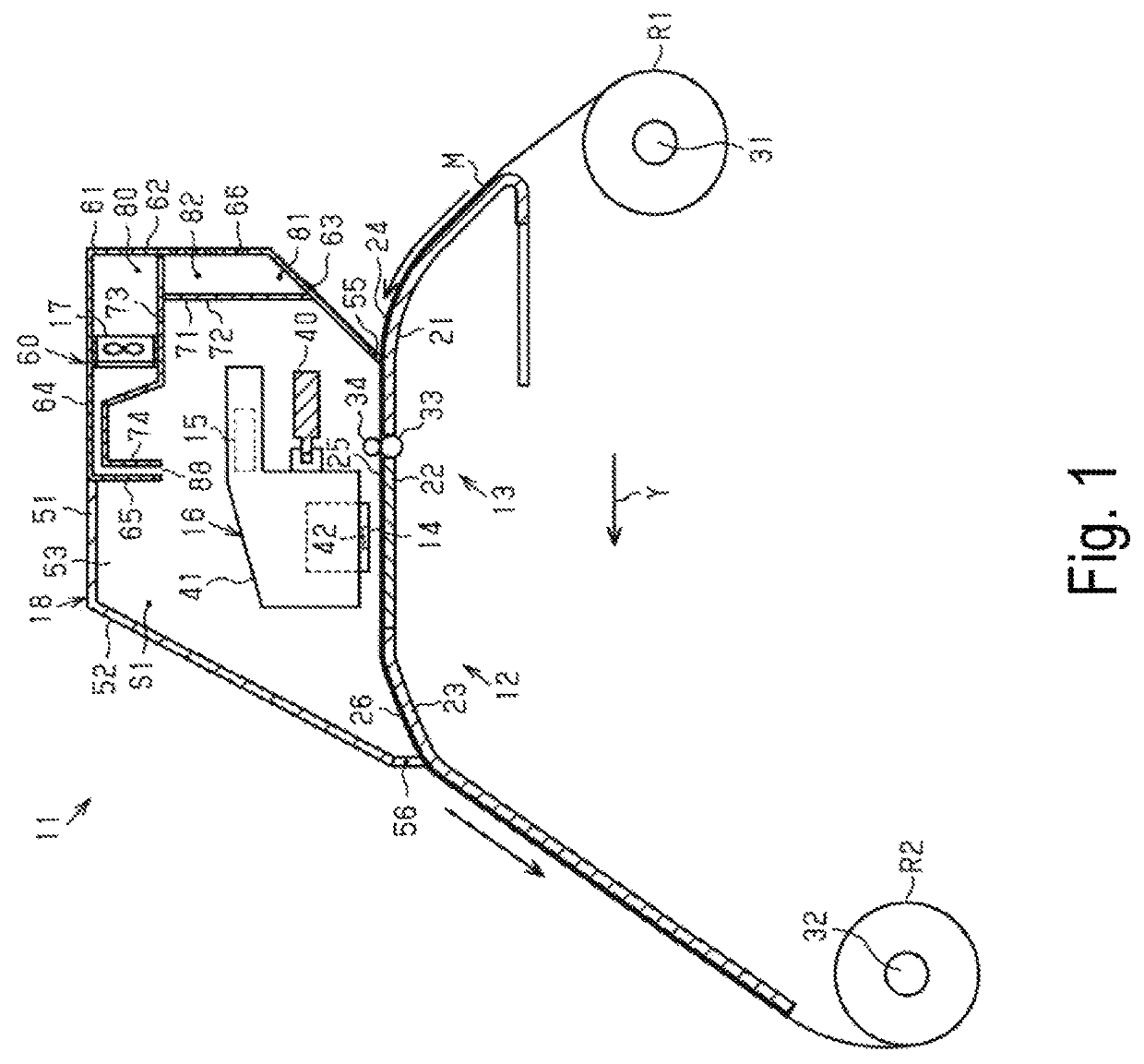
[0020]Now, description is made of an exemplary embodiment of a printing apparatus. Note that, in the following description, “upper” indicates an upper side in the vertical direction, and “lower” indicates a lower side in the vertical direction.

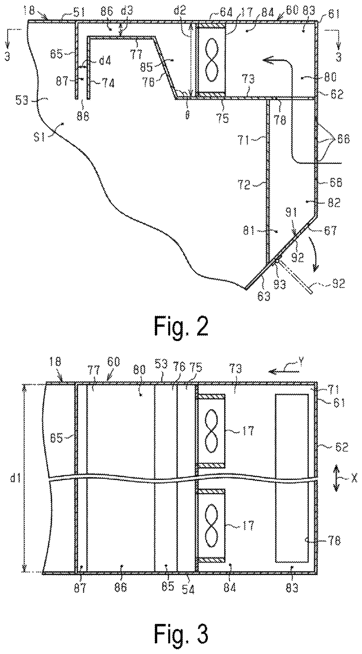
[0021]As illustrated in FIG. 1 and FIG. 2, a printing apparatus 11 includes a support unit 12 capable of supporting a medium M, a transport unit 13 configured to transport the medium M along the support unit 12, a printing unit 14 configured to perform printing on the medium M, a drive circuit 15 configured to drive the printing unit 14, a moving mechanism 16 configured to move the printing unit 14, and blower units 17 configured to send gas onto the medium M. The printing apparatus 11 includes a housing 18 configured to contain the printing unit 14, the moving mechanism 16, and the blower units 17. The printing apparatus 11 is, for example, an ink jet-type printer that prints an image such as characters and photographs on the medium M by caus...


PUM


Abstract

A printing apparatus includes: a printing unit configured to perform printing on a medium; a flow path including a blowout port and an intake port, the blowout port being configured to send gas toward the medium from an upper side of the printing unit in a vertical direction, the intake port being configured to take in outside air; a blower unit arranged in the flow path and configured to generate a gas flow passing from the intake port toward the blowout port; and a housing configured to contain the printing unit and the blower unit and form the flow path. The flow path includes a vertical portion between the intake port and the blower unit where the gas flows in a direction against the gravity.

Description

BACKGROUND1. Technical Field[0001]The present invention relates to a printing apparatus.2. Related Art[0002]JP-A-2017-128060 discloses a printing apparatus including a printing unit for performing printing on a medium, a blower unit for sending gas onto the medium, and a housing for storing the printing unit. The printing unit performs printing on the medium by causing liquid to adhere to the medium. The blower unit promotes drying of the medium by sending gas onto the medium. Further, the printing apparatus disclosed in JP-A-2017-128060 includes a gas sending / sucking mechanism. The gas sending / sucking mechanism causes the gas to circulate by sucking the gas inside the housing and returning the sucked gas to the inside of the housing.[0003]As described in JP-A-2017-128060, when the gas inside the housing is caused to circulate, humidity of the circulating gas is increased due to evaporation of the liquid adhering to the medium. When the humidity of the gas increases, degradation of ...

Claims


Application Information

Patent Timeline
Patent Type & Authority Patents(United States)
IPC IPC(8): B41J11/00B41J29/377B41J29/13
CPCB41J29/377B41J11/00B41J29/13B41J11/0022
Inventor ASAMOTO, KATSUYA
Owner SEIKO EPSON CORP
Why Eureka
Try Eureka