
Catwalk tubular measurement and method of use

a technology of tubular measurement and catwalk, which is applied in the direction of drilling rods, drilling pipes, drilling casings, etc., can solve the problem of inaccurate pipe tally databas

Active Publication Date: 2021-02-23
NABORS DRILLING TECH USA INC
View PDF5 Cites 3 Cited by
  • Summary
  • Abstract
  • Description
  • Claims
  • Application Information

AI Technical Summary

Benefits of technology

The patent text describes a carrier assembly for moving tubular members, such as drilling rig equipment, using a carrier and skate system. The assembly includes a proximity sensor and skate position sensor that work together to detect and measure the position of the tubular member during movement. This allows for precise placement and alignment of the tubular member, which can improve the efficiency and safety of drilling operations. The technical effect of this invention is to provide a reliable and efficient method for moving and positioning tubular members in drilling rigs.

Problems solved by technology

Such a process is laborious as tubular members are not always the same length due to recuts and special-order lengths, and the pipe tally database may be inaccurate due to human error.

Method used


Image

  • Catwalk tubular measurement and method of use
  • Catwalk tubular measurement and method of use
  • Catwalk tubular measurement and method of use

Examples


Embodiment Construction

[0011]It is to be understood that the following disclosure provides many different embodiments, or examples, for implementing different features of various embodiments. Specific examples of components and arrangements are described below to simplify the present disclosure. These are, of course, merely examples and are not intended to be limiting. In addition, the present disclosure may repeat reference numerals and / or letters in the various examples. This repetition is for the purpose of simplicity and clarity and does not in itself dictate a relationship between the various embodiments and / or configurations discussed.

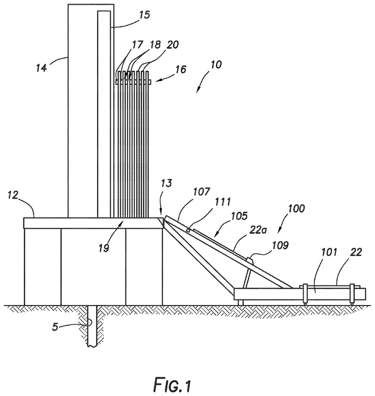
[0012]FIG. 1 depicts drilling rig 10 positioned to perform wellbore operations on wellbore 5. Drilling rig 10 may include drill floor 12 and mast 14. Drilling rig 10 may include V-door 13. V-door 13, as understood in the art, may be an opening in or open area of drill floor 12 through which tubular members may be introduced to drilling rig 10 from catwalk assembly 100 ...


PUM


Abstract

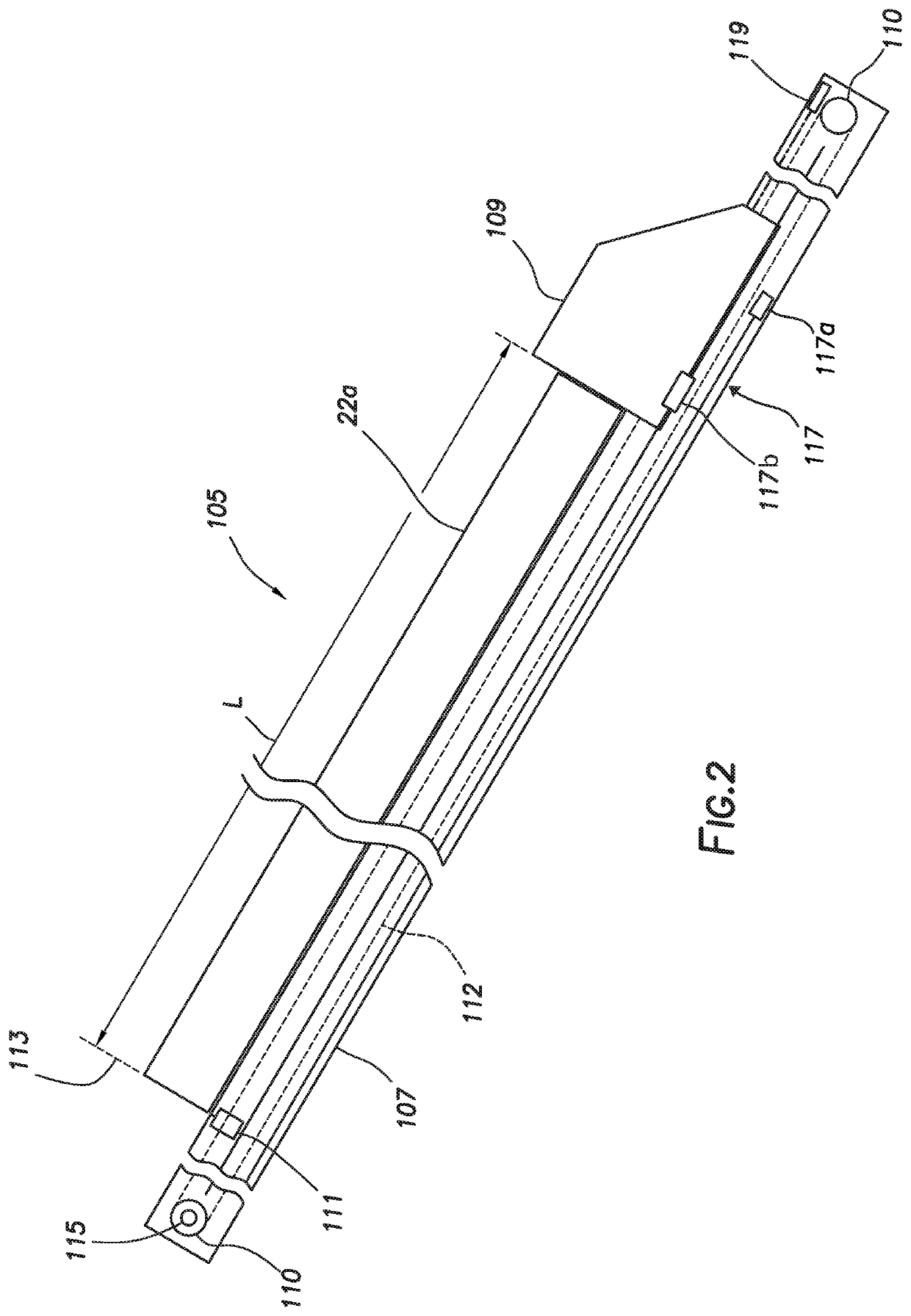
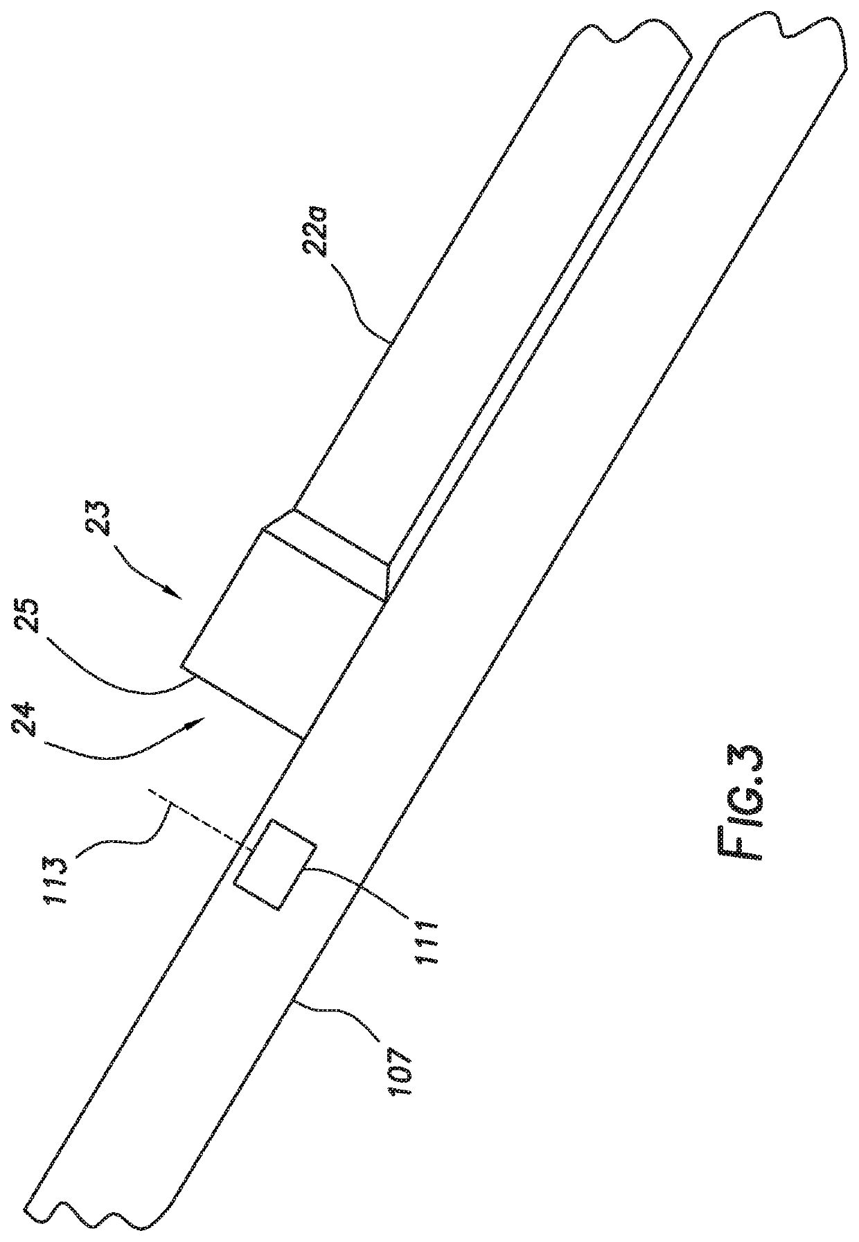
A carrier assembly for a catwalk assembly includes a carrier. The carrier assembly includes a skate to move a tubular member along the carrier. The carrier assembly includes a proximity sensor positioned to detect the end of the tubular member as it moves along the carrier. The carrier assembly includes a skate position sensor. The length of the tubular member may be determined by measuring the position of the skate relative to the proximity sensor when the end of the tubular member passes the proximity sensor.

Description

CROSS-REFERENCE TO RELATED APPLICATION[0001]This application is a nonprovisional application that claims priority from U.S. provisional application No. 62 / 607,186, filed Dec. 18, 2017, the entirety of which is hereby incorporated by reference.TECHNICAL FIELD / FIELD OF THE DISCLOSURE[0002]The present disclosure relates generally to drilling rig equipment, and specifically to methods and apparatuses for tubular length measurement.BACKGROUND OF THE DISCLOSURE[0003]When performing a wellbore operation such as a drilling operation, a tubular string may be introduced into the wellbore. Typically, the tubular string includes a plurality of tubular members and other downhole tools joined end-to-end by threaded joints to extend into the wellbore. Tubular members, as used herein, include but are not limited to drill pipes, casings, and other tools threadedly connected to the tubular string. These tubulars are normally assembled in groups of two or more—commonly known as “stands”—to be vertical...

Claims


Application Information

Patent Timeline
Patent Type & Authority Patents(United States)
IPC IPC(8): E21B19/16E21B15/00E21B19/02E21B17/00E21B19/15
CPCE21B19/16E21B15/00E21B19/02E21B19/165E21B17/006E21B19/15E21B19/14E21B19/00
Inventor MAGNUSON, CHRISTOPHERSAZO, MARIOKUNEC, ALEX
Owner NABORS DRILLING TECH USA INC
Learn More