Variable geometry airframe for vertical and horizontal flight

a variable geometry, vertical and horizontal flight technology, applied in the direction of vertical landing/take-off aircraft, transportation hydrogen technology, transportation and packaging, etc., can solve the problems of rotor-based aircraft being overcome, unable to multi-directional maneuverability of fixed-wing aircraft, limited forward speed and endurance, etc., to reduce the amount of leading edge, the effect of stable transition

Active Publication Date: 2021-03-02
BIO CELLULAR DESIGN AERONAUTICS AFRICA SA
View PDF26 Cites 2 Cited by
  • Summary
  • Abstract
  • Description
  • Claims
  • Application Information

AI Technical Summary

Benefits of technology

[0005]In one particular embodiment, the present invention is directed to an airframe equipped with at least one hybrid wing configured to alter its surface area and leading edge position in order to allow for a stable transition from vertical takeoff and landing (VTOL) flight and forward flight (FF). With specific reference to an un-manned aerial vehicle, the present invention is directed to an aircraft configured for both VTOL and FF flight. By using pivoting airfoils, or wings, the aircraft is able to reduce the amount of leading edge presented to the direction of travel, thus presenting a smaller cross section during vertical takeoff and landings.
[0006]Once the aircraft has reached a suitable height and position, the wings pivot or other wise move to align the leading edges of the wings with the direction of forward flight. In order to provide sufficient lift at slow speeds during the transition, the wings are further configured to increase the wing surface area by extruding or expanding low speed wing extensions from the wings. The low speed wing extensions are, in one arrangement, inflatable or air-ram based fabric sleeves that increase the surface area of the wing and provide more lift at low to medium speeds. Once the aircraft gains sufficient speed, the wing extensions are retracted and the aircraft is able to engage in forward flight as a fixed wing aircraft.
[0007]The unique and advanced configuration provided herein, offers significant advantages over conventional airframes and allows for the minimization of negative drag coefficients during flight, maximizing of usable ranges and minimizing of energy requirements.

Problems solved by technology

However, fixed wing aircraft lack multi-directional maneuverability and require significant runway and landing infrastructure.
Rotor-based aircraft overcome these drawbacks but are limited in forward speed and endurance.
Existing VTOL aircraft usually have large power plants and fuel requirements.

Method used


Image

  • Variable geometry airframe for vertical and horizontal flight
  • Variable geometry airframe for vertical and horizontal flight
  • Variable geometry airframe for vertical and horizontal flight

Examples


Embodiment Construction

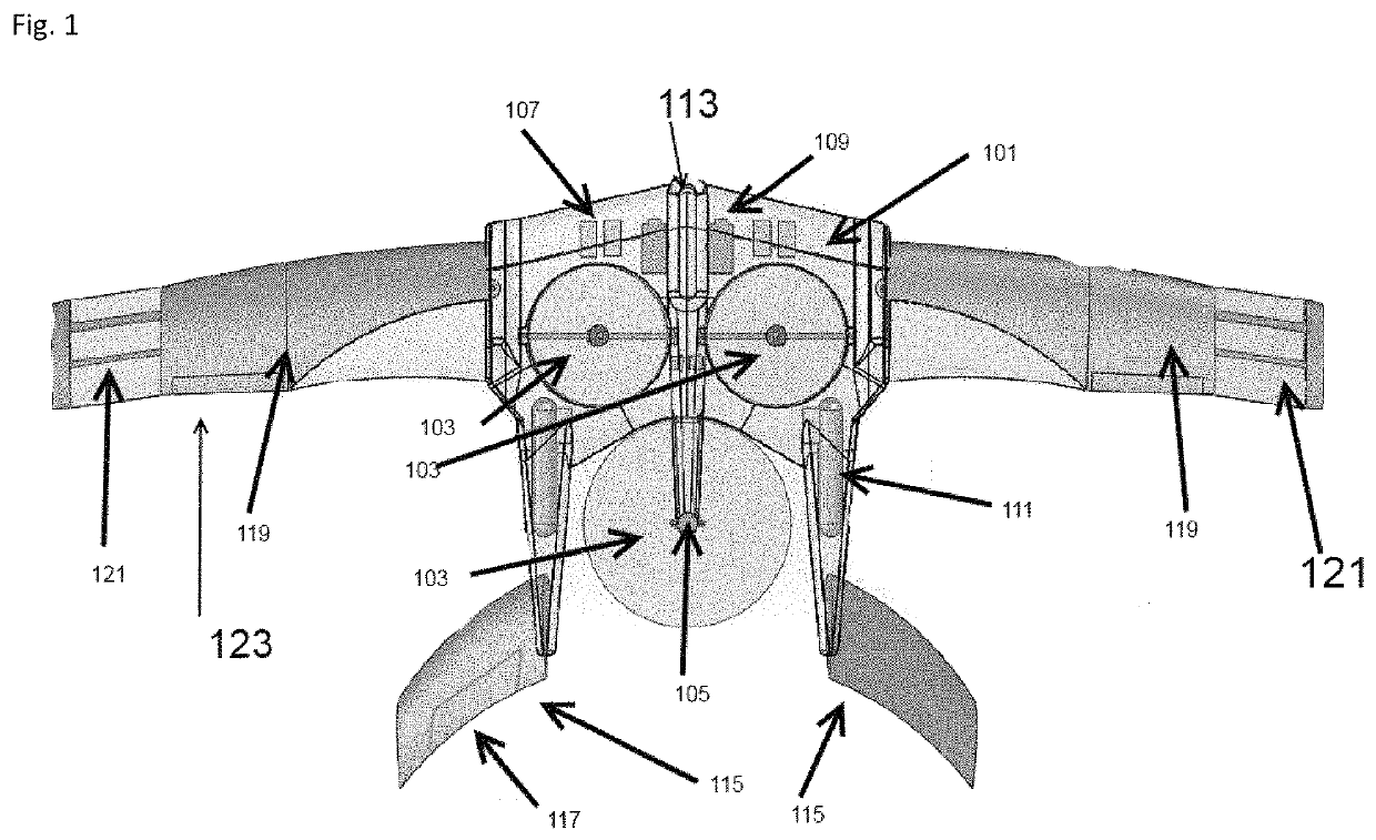
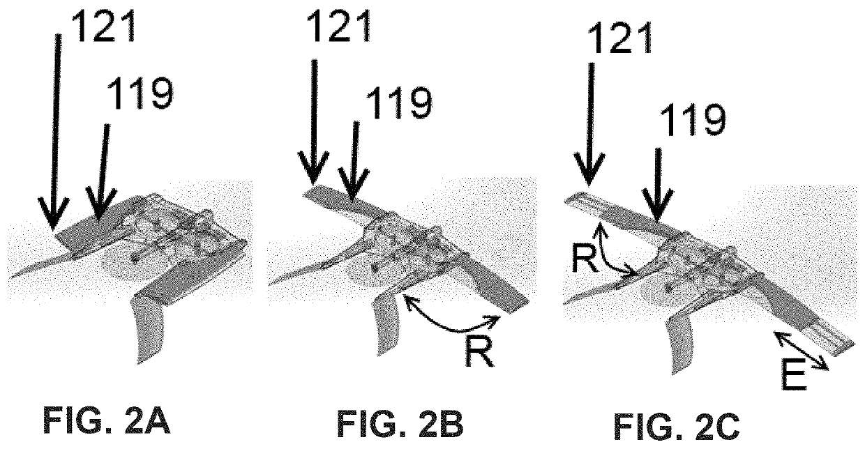
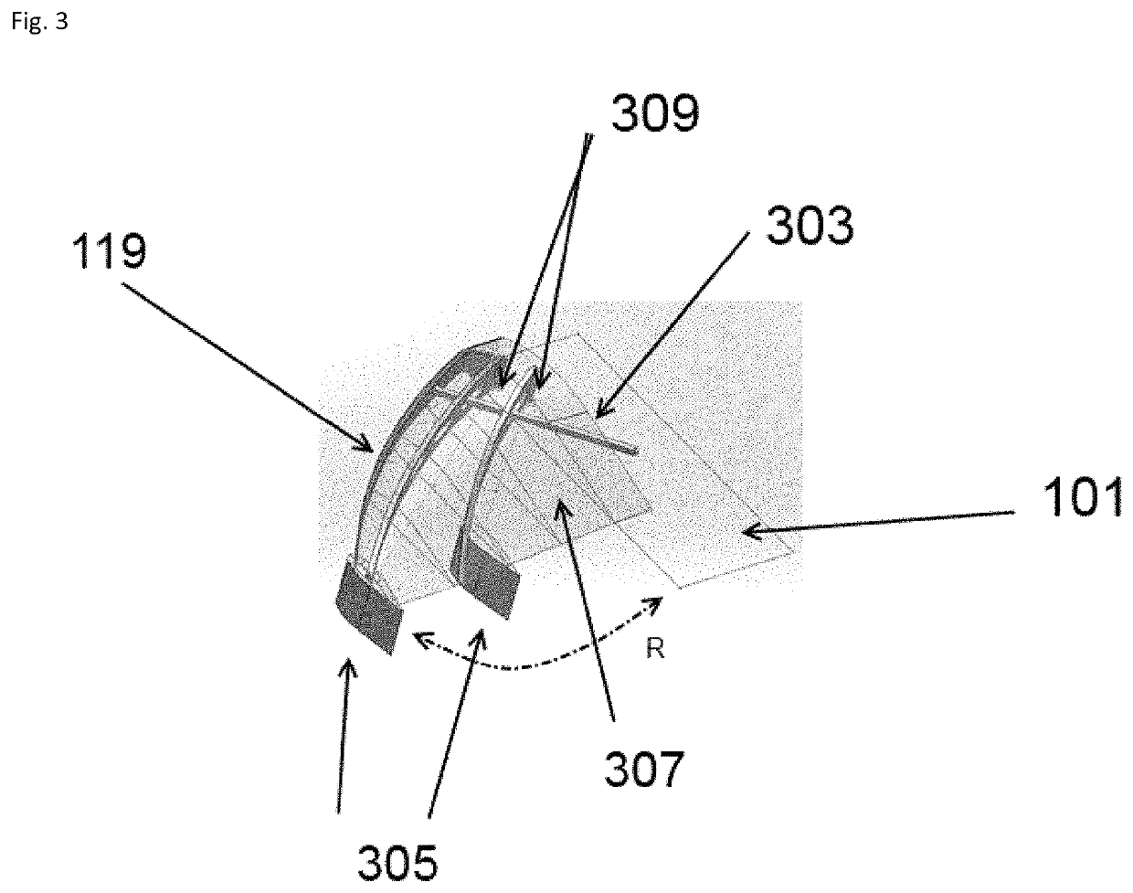
[0016]By way of overview and introduction, the present invention is directed to a vertical takeoff and landing (VTOL) device in the form of an unmanned aerial vehicle (UAV) that implements a hybrid wing design that allows for improved VTOL performance as well as improved forward flight (FF) performance. The UAV uses a folding and extensible wing configuration to improve lift and drag performance relative to fixed wing or rotor winged aircraft. Those possessing an ordinary level of skill in the art will appreciate that the present embodiments have a broader applicability in the field of air-borne vehicles. Particular configurations discussed in examples can be varied and are cited to illustrate the principles of exemplary embodiments

[0017]With reference to FIGS. 1 and 2, the present invention is directed to an airframe 101. In a particular arrangement, the airframe 101 is formed out of carbon fiber or a similar material having a high strength to weight ratio. In another configuration...


PUM


Abstract

A hybrid wing autonomous aircraft having, an airframe, at least one hybrid wing member having an airframe end and an extended end, and having leading and trailing edges and a plurality of control structures, the airframe end coupled to the airframe, and the extended end further configured with a wing extension device, the wing extension device configured to extend a supplemental lifting surface from the extended end, an airframe actuator configured to cause the extension end of the hybrid wing member to move from a first position relative to the airframe to a second position relative to the airframe, wherein the second position is greater in distance from the airframe than the first position.

Description

FIELD OF THE INVENTION[0001]The present invention relates to morphing wing designs for use with aircraft designed to engage in both vertical takeoff and landing (VTOL) operations as well as forward flight operations. The airframe includes wings configured to control the direction of the leading edge of a wing as well as increase the surface area of the wing during low speed transitions to and from VTOL to normal flight.BACKGROUND OF THE INVENTION[0002]Typically, fixed wing aircraft are extremely efficient for long-distance flight applications and maintain a simple control scheme. However, fixed wing aircraft lack multi-directional maneuverability and require significant runway and landing infrastructure. Rotor-based aircraft overcome these drawbacks but are limited in forward speed and endurance.[0003]Existing VTOL aircraft usually have large power plants and fuel requirements. For instance, many VTOL aircraft use ducted fan arrangements to implement thrust vectoring to maintain air...

Claims


Application Information

Patent Timeline
Patent Type & Authority Patents(United States)
IPC IPC(8): B64C3/54B64C39/02B64C29/00B64D41/00
CPCB64C3/546B64C29/0025B64C29/0033B64C39/024B64C2201/021B64C2201/042B64C2201/088B64C2201/102B64D2041/005Y02T50/10Y02T90/40B64U30/12B64U50/32B64U10/20B64U60/50B64U30/26B64U10/25B64U50/19B64U70/80
Inventor RATTI, JAYANT
Owner BIO CELLULAR DESIGN AERONAUTICS AFRICA SA
Why Eureka
Try Eureka