Simple vehicle rack

a vehicle rack and simple technology, applied in vehicle components, transportation and packaging, supplementary fittings, etc., can solve the problems of limiting the width of goods placed, the bolt of the fixed seat cannot be fixed, and the tie rope fixed on the two fixed racks cannot compact the vehicl

Active Publication Date: 2021-03-09
FORCOME ZHEJIANG CO LTD
View PDF33 Cites 4 Cited by
  • Summary
  • Abstract
  • Description
  • Claims
  • Application Information

AI Technical Summary

Benefits of technology

[0012]Compared with the prior art, the advantages of the present application are as follows: 1. The space between the two fixed frames can be adjusted to suit more specifications of cargo carrier; 2. The design of multi-height fixed holes makes the goods of various heights more firmly bound. 3. The fixed point of the fixed seat can be changed, so that it can be fixed around obstacles without changing the position of the support frame and the fixed seat body, so that the support frame can be fixed more reasonably.

Problems solved by technology

When the fixed frame set in this way adjusts the space between the two fixed frames, when the fixed frame slides to the fixed point of the support frame, it cannot slide to the end of the fixing rod outside the support frame, but can only be fixed to the inside of the support frame, which greatly limits the width of goods placed.
Secondly, there is only one fixed hole on the fixed pole of the existing vehicle rack, and the position is higher than that of the fixed pole.
When the vehicle is flat, the tie rope fixed on the two fixed racks cannot compact the vehicle.
If the fixed seat is fixed on the vehicle trailer fence board, the fastening bolt is fixed in the same position as the pull rope on the vehicle trailer fence board, and the fastening bolts of the fixed seat are fixed in the same position, and the bolt of the fixed seat cannot be fixed.
Therefore, the support frame and the fixed seat must be moved, which is not only troublesome, but also may lead to inappropriate fixed position of the support frame.

Method used


Image

  • Simple vehicle rack
  • Simple vehicle rack
  • Simple vehicle rack

Examples


embodiment 1

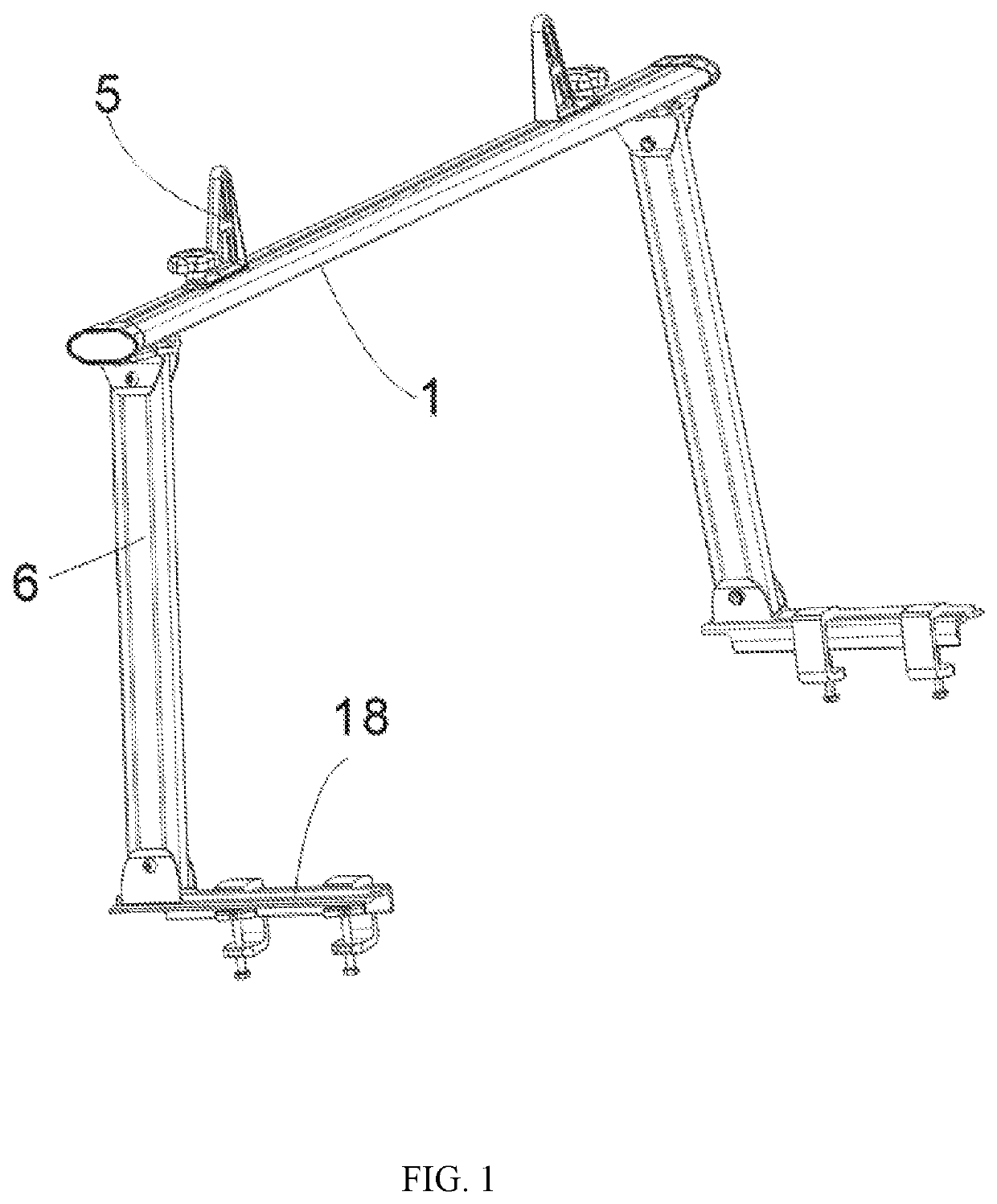
[0022]Referring to FIG. 1, the simple vehicle rack provided by the present embodiment consists of a fixed pole 1, a fixed frame 5, a support frame 6 and a fixed seat 18, among them, the fixed frame 5, the support frame 6 and the fixed seat 18 are two. The two fixed frame 5 are movably fixed at the top of the fixed pole 1, and two support frames 6 are movably fixed at the bottom of the fixed pole 1. Meanwhile, a fixed seat 18 is fixed on each support frame 6.

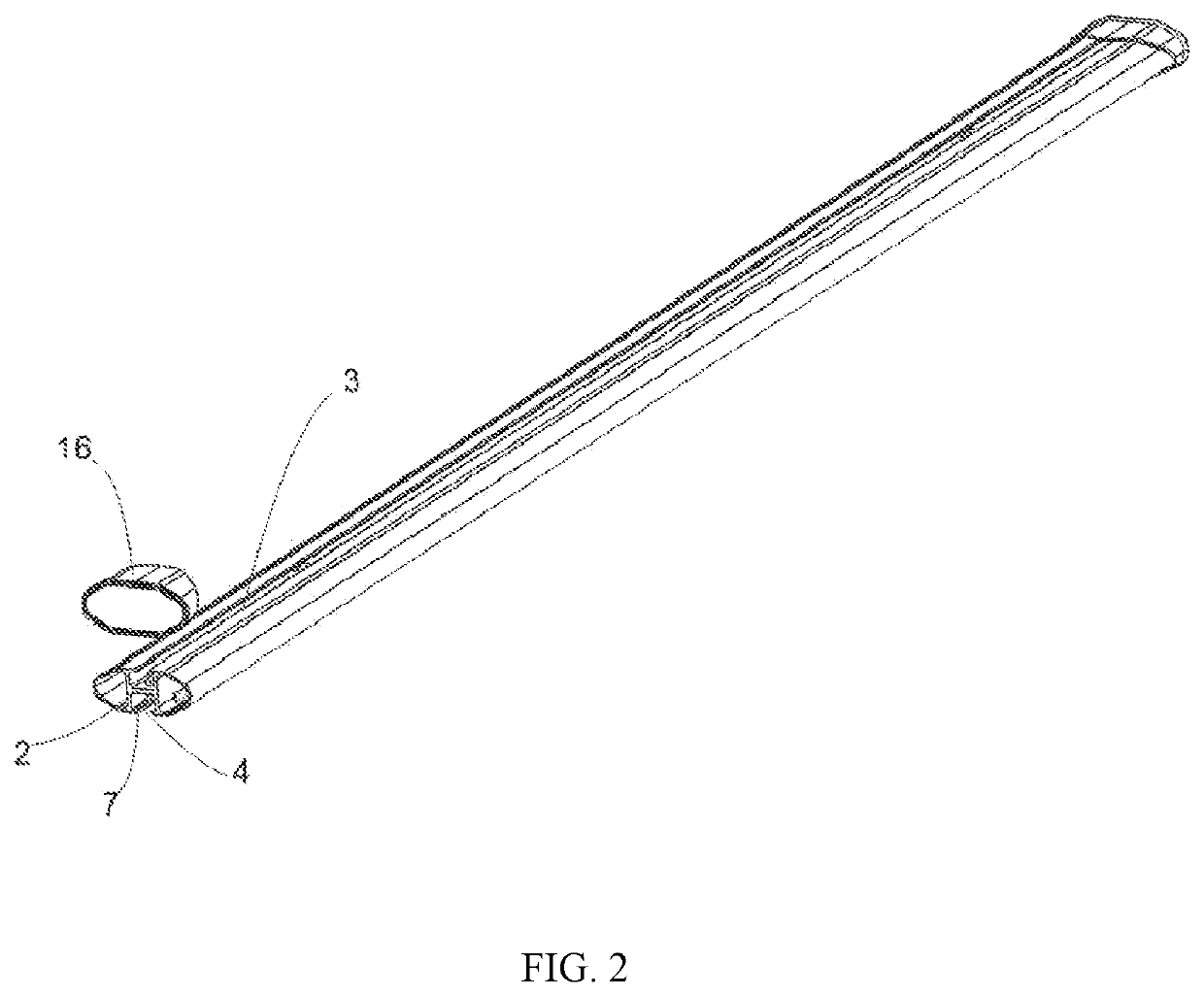
[0023]Referring to FIG. 2, the fixing rod 1 is a hollow aluminum alloy tube. The center of the tube body is a H-shaped reinforcing seat 2. The H-shaped reinforcing seat 2 makes the upper and lower sides of the aluminum alloy tube plane form an upper sliding slot 3 and a lower sliding slot 4 along the length of the aluminum alloy tube. At the same time, the upper sliding slot 3 and the lower sliding slot 4 extend with corresponding locking sheets 7. Meanwhile the closed cover 16 is fixed on the left and right sides of the fixing r...


PUM


Abstract

A simple vehicle rack includes: a fixing rod, a middle part of the fixing rod being an H-shaped reinforcing seat, the H-shaped reinforcing seat forming an upper sliding slot on a top surface of the fixing rod and forming a lower sliding slot on a bottom surface of the fixing rod; two fixing frames, the fixing frames being fixed on the top surface of the fixing rod and connected to the fixing rod, moving back and forth along the upper sliding slot; and two support frames, the support frames being fixed on the bottom surface of the fixing rod and connected to the fixing rod, moving back and forth along the lower sliding slot.

Description

[0001]This application claims priority to Chinese Patent Application No.: 201920994826.2, filed on Jun. 28, 2019, which is incorporated by reference for all purposes as if fully set forth herein.TECHNICAL FIELD[0002]This application relates to a simple vehicle rack.BACKGROUND TECHNOLOGY[0003]The existing simple vehicle rack consists of a fixing rod with support at the bottom of both ends of the fixing rod, a fixed seat at the bottom of the supporting rod. The fixed seat is fixed on the vehicle trailer. A fixed frame for the fixing of the binding rope on the fixing rod. A slot is arranged along the length of the fixing rod of the existing simple vehicle shelf. The upper end of the support frame is connected to the sliding slot of the fixing rod through bolts and clamping plates, and the two fixing frames above the fixing rod are also provided on the sliding slot of the fixing rod. When the fixed frame set in this way adjusts the space between the two fixed frames, when the fixed fram...

Claims


Application Information

Patent Timeline
Patent Type & Authority Patents(United States)
IPC IPC(8): B60R9/058B60R9/00
CPCB60R9/058B60R9/00
Inventor NI, XIAOJUNFANG, CHENGSHENGXIONG, JINGWANG, JIANCHENG
Owner FORCOME ZHEJIANG CO LTD
Why Eureka
Try Eureka