Hand grip for transmitting stress through a hand strap to a wrist strap

a technology for transmitting stress through a hand strap and a wrist strap, which is applied in the field of hand grips to achieve the effects of firm and maintained stress transfer positioning of the hand strap, strong and reliable, and preventing unwanted release of the outer portion

Active Publication Date: 2021-03-16
STAROMINSKY DIMITRY
View PDF11 Cites 6 Cited by
  • Summary
  • Abstract
  • Description
  • Claims
  • Application Information

AI Technical Summary

Benefits of technology

[0005]The present invention provides a stronger and more reliable way of maintaining the hand strap in stress transferring position. This is accomplished by securing a firm, elongated block to the hand strap outer portion. The block projects outwardly across the outer portion and has a flat front surface and a flat outer surface forming an edge for engagement under the knuckle of the distal phalanx of at least one finger of the wearer. Thereby, providing for firm bent finger engagement of the block edge to prevent unwanted release of the outer portion out of stress transferring position. The known hand grips and gloves do not disclose or suggest this block edge engagement that provides firm and maintained stress transferring positioning of the hand strap.
[0007]In the preferred embodiment, the block is of sufficient upstanding extent to prevent engagement by the distal phalanx of the fingers with the outer portion of the hand strap sufficient to lessen the gripping of the block by the fingers, and the block is secured to the outer surface of the outer portion of the hand grip by a cover layer secured to the outer surface of the and extending over the block to secure the block to the outer portion.

Problems solved by technology

The known hand grips and gloves do not disclose or suggest this block edge engagement that provides firm and maintained stress transferring positioning of the hand strap.

Method used


Image

  • Hand grip for transmitting stress through a hand strap to a wrist strap
  • Hand grip for transmitting stress through a hand strap to a wrist strap
  • Hand grip for transmitting stress through a hand strap to a wrist strap

Examples


Embodiment Construction

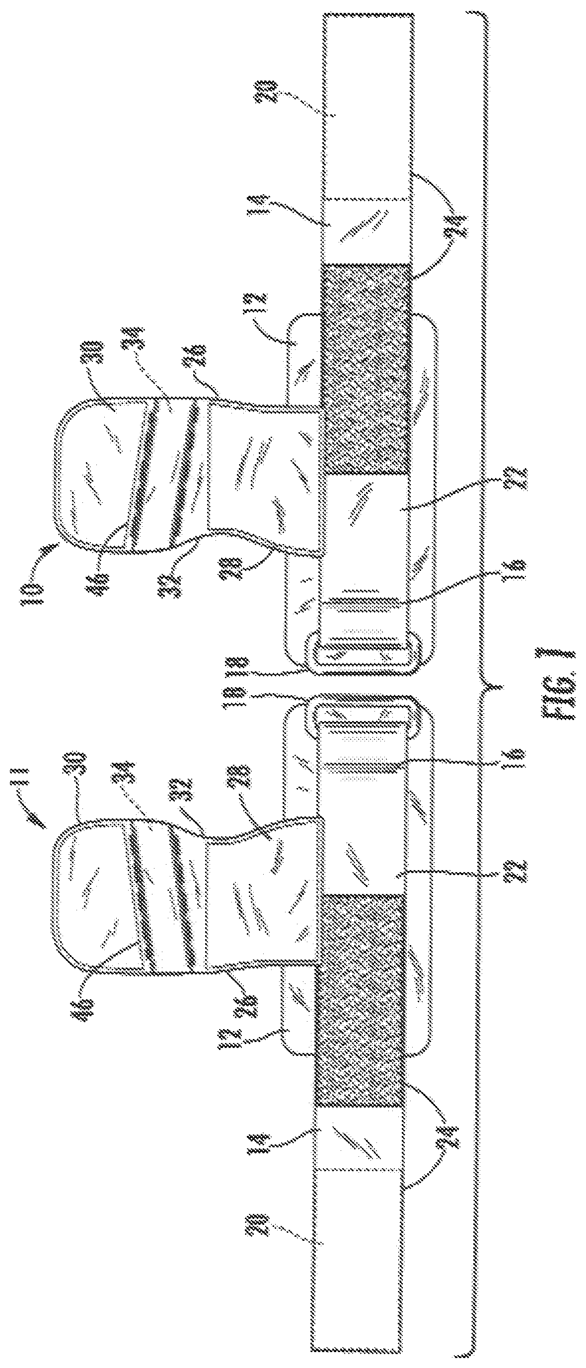
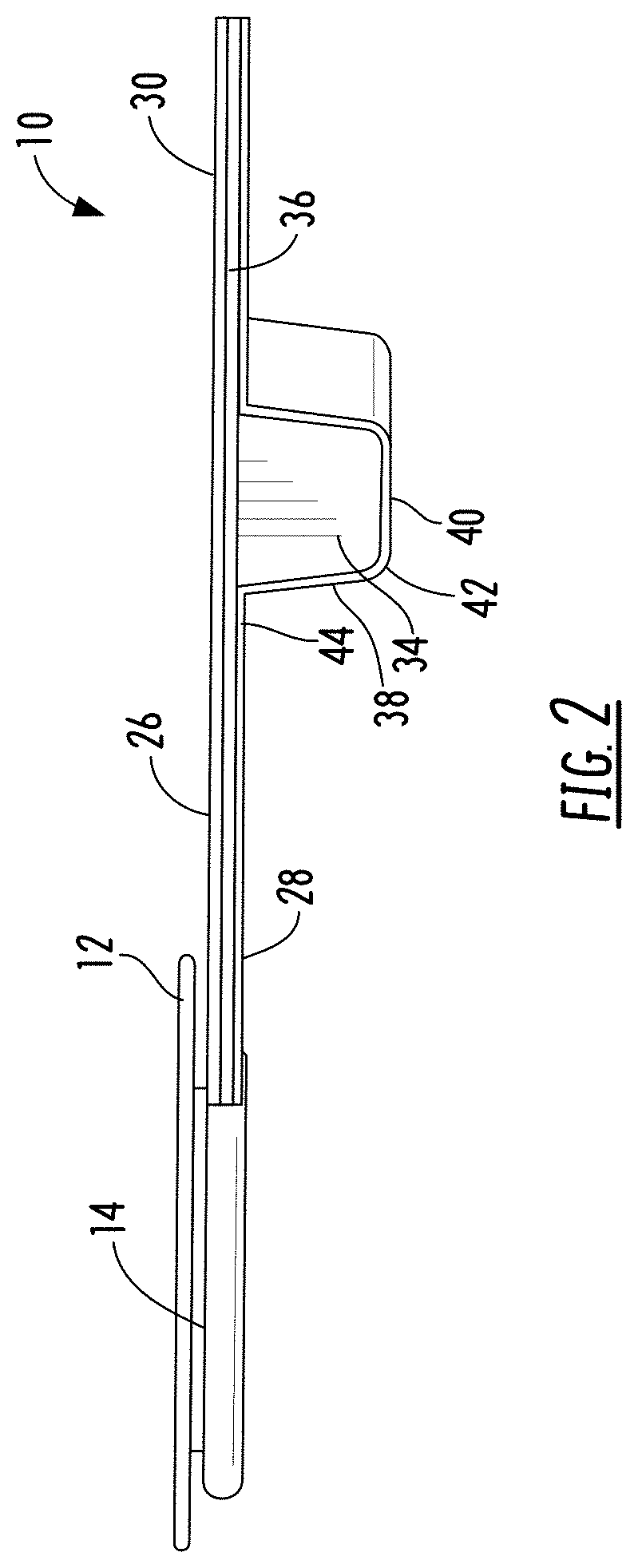
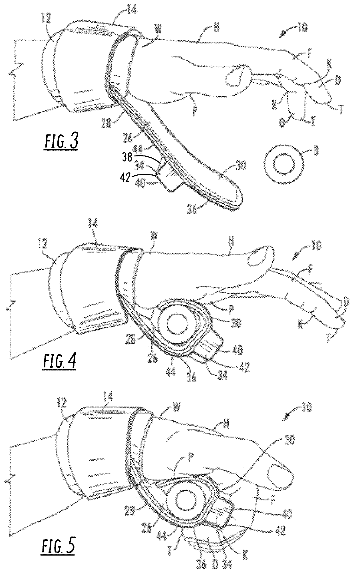
[0017]The preferred embodiment of the present invention is illustrated in the accompanying drawings. It consists of a pair of hand grips, one hand grip 10 for the left hand of the wearer, as illustrated at the left of FIG. 1, and the other hand grip 11 for the right hand of the wearer, as illustrated at right of FIG. 1. The two hand grips, 10 and 11, are identical mirror images of each other and the identical elements of the two are identified by the same reference numbers. The pair is adapted for use in performing gymnastic weight lifting with both hands.

[0018]Each hand grip 10 and 11 includes a flexible wrist strap 12 that wraps around the wrist W of a wearer and is secured tightly by an elongated band 14 that has an inner portion 16 secured in a metal ring 18 that is attached to the outside of the wrist strap 12. The outer portion 22 of the band 14 extends away from the ring 18 and around the wrist strap 12 to the ring 18, and is looped through the ring 18 and back along the inne...


PUM


Abstract

A hand grip for transmitting tensile stress through a hand strap from an object, such as the bar of a barbell, being gripped to the wrist of the wearer without stressing the hand of the wearer, and extending around the bar of the barbell between the bar and the palm of the wearer. A block of relatively firm material is secured to and projects from the hand grip in a position to be engaged by the fingers of the wearer to lessen the possibility of the hand grip opening to release the bar of the barbell. The block has a flat front and a outer surfaces forming an edge for engagement under the knuckle of at least one finger of the hand of the wearer, and the front surface projects from the hand strap sufficiently to avoid lessening the grasp of the block by the fingers of the wearer.

Description

FIELD OF THE INVENTION[0001]The present invention relates to hand grips that are used to transmit the tensile stress of lifting or pulling loads through a hand strap to a wrist strap without stressing the hand of the wearer.BACKGROUND OF THE INVENTION[0002]When hands are used to lift or pull objects, tensile stress is created in the muscles of the fingers and hands as well as in the arms, legs and core muscles. As the muscles of the fingers and hands are not as large and therefore not as strong as the muscles of the arms, legs and core, the muscles of the hands limit the amount of force that can be applied for lifting and pulling. In particular, in weightlifting gymnastic exercises and in competition using barbells, the amount of weight that can be lifted is limited by the strength of the fingers and hands.[0003]As a result, handgrips and gloves have been devised that bypass the fingers and hands in the application of stress by connecting directly the tensile stress created by the l...

Claims


Application Information

Patent Timeline
Patent Type & Authority Patents(United States)
IPC IPC(8): A63B21/00A63B21/06A41D19/015
CPCA63B21/4021A41D19/01547A63B21/06A63B21/4019A63B2209/10A63B21/0724A63B71/00
Inventor STAROMINSKY, DIMITRY
Owner STAROMINSKY DIMITRY
Why Eureka
Try Eureka