Method and system for controlling a vehicle tire-to-road friction estimation

a technology of vehicle tire-to-road friction and estimation method, which is applied in the direction of process and machine control, transportation and packaging, instruments, etc., can solve the problems of disturbing the driver and the surrounding road users, the vehicle speed must be lower and maybe too low for driver acceptance, and the difficulty of getting reliable estimates of tire-to-road friction

Active Publication Date: 2021-04-06
VOLVO CAR CORP
View PDF8 Cites 0 Cited by
  • Summary
  • Abstract
  • Description
  • Claims
  • Application Information

AI Technical Summary

Benefits of technology

[0010]Accordingly, present invention is based on the realization that it is not always required to perform a friction measurement when approaching a curve, and that it in many situations is possible to perform the friction measurement during normal driving of the vehicle if a friction measurement is required. For example, many drivers will slow down enough ahead of a curve such that a friction measurement can be performed during driver initiated braking. Unless the friction measurement is performed during driver initiated braking, a non-braking friction measurement is advantageously employed to minimize the influence on the vehicle experienced by the driver. Hence, unnecessary friction measurements can be avoided, the number of performed friction measurements is minimized, and the driver inconvenience of forced friction measurement is minimized.
[0011]Hereby, it can be ensured that a friction value which is as correct as possible is used to determine the maximum allowable vehicle speed when reaching the curve entrance for preventing that the vehicle loses grip in the curve. It is here assumed that the tire-to-road friction in the curve does not differ significantly from the tire-to-road friction before the curve. In other words, the described method is not intended to account for unexpected and transient events influencing the friction properties of the curve, such as oil spills or ice patches. It is also assumed that the speed of the vehicle when entering the curve, i.e. the maximum allowable vehicle speed, can be safely maintained throughout the curve. Moreover, even if the vehicle was to lose the grip in the curve, other vehicle systems are assumed to take control, such as electronic stability control (ESC) systems.
[0013]According to one embodiment of the invention, the method may further comprise, if the current vehicle speed is higher than the maximum allowable vehicle speed, braking the vehicle with a constant deceleration from the current location of the vehicle to the curve entrance so that the vehicle speed is equal to or lower than the determined maximum allowable vehicle speed when the vehicle reaches the curve entrance. By braking with a constant deceleration, a smooth and comfortable braking experience is achieved.
[0020]According to one embodiment of the invention, the method may further comprise estimating a vehicle path through the curve based on the curve properties. Thereby, the vehicle speed can be adapted to an estimated and preferably optimized path through the curve, where the path can be refined depending on how much information describing the curve properties is available. A path through the curve may for example include cutting the curve so that the vehicle is not always in the middle of the lane. This may allow the vehicle to travel through the curve in a manner which is more similar to how a driver would drive through the curve, thereby providing a more familiar user experience.

Problems solved by technology

Large friction uncertainty means that vehicle speed must be lower and maybe too low for driver acceptance.
Getting reliable estimates of the tire-to-road friction is commonly known to be more difficult.
The easiest way is brake fully and measure the deceleration, but this would be disturbing to the driver and to surrounding road users.
However, the driver and passengers may possibly notice the measurements through the sound of the braking / propulsion system.
Moreover, if the measurements are performed frequently, they will have a negative effect on the fuel consumption.
However, during normal driving, the driver may still notice that a friction measurement is performed.
In other words, the described method is not intended to account for unexpected and transient events influencing the friction properties of the curve, such as oil spills or ice patches.

Method used


Image

  • Method and system for controlling a vehicle tire-to-road friction estimation
  • Method and system for controlling a vehicle tire-to-road friction estimation
  • Method and system for controlling a vehicle tire-to-road friction estimation

Examples


Embodiment Construction

[0029]The present invention will now be described more fully hereinafter with reference to the accompanying drawings, in which currently preferred embodiments of the invention are shown. This invention may, however, be embodied in many different forms and should not be construed as limited to the embodiments set forth herein; rather, these embodiments are provided for thoroughness and completeness, and fully convey the scope of the invention to the skilled person. Like reference characters refer to like elements throughout.

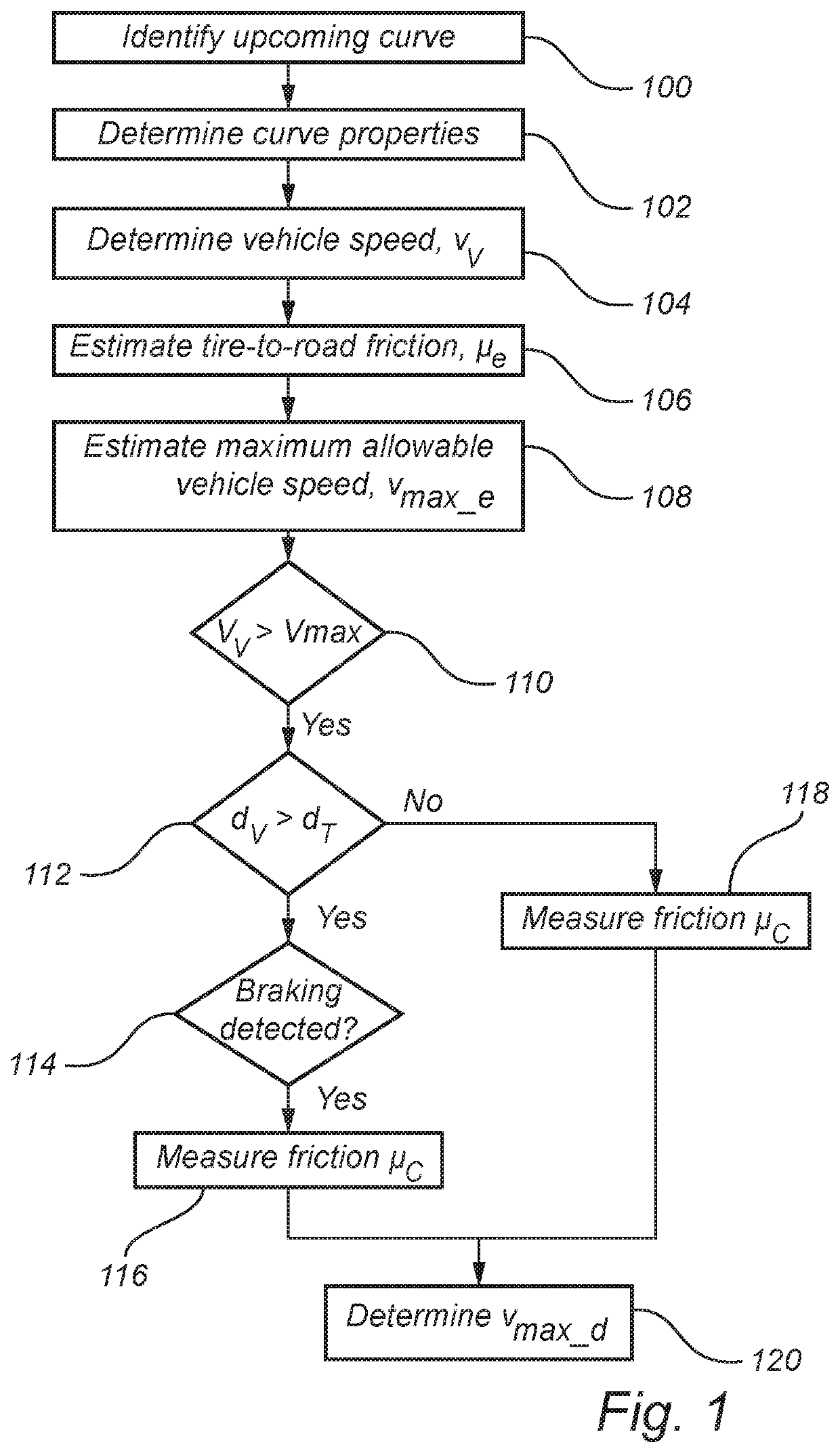
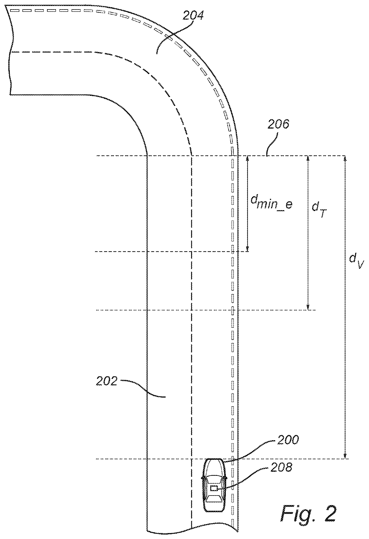
[0030]FIG. 1 is a flow chart outlining the general steps of a method of controlling a vehicle 200 according to an embodiment of the invention; and the method will be described with further reference to FIG. 2 schematically illustrating the method performed by a vehicle 200.

[0031]The method is applied when a vehicle is travelling on a road 202 and approaching a curve 204 in the road 202. In particular, the method is aimed at determining if and where it is necessary...


PUM


Abstract

Method for controlling a vehicle, comprising: identifying an upcoming curve and determining its properties; determining current vehicle speed, vv, estimating friction, μe, between a tire of the vehicle and the road; estimating maximum allowable vehicle speed, vmax_e, when entering the curve based on the properties, speed and friction; if the current vehicle speed is higher than the estimated maximum allowable vehicle speed, determining that a friction measurement is required; if distance, dv, between the vehicle and a curve entrance is higher than a predetermined threshold distance, dT, and if a braking action is detected, performing a friction measurement during the braking action to determine current friction, μc; if a distance between the vehicle and the curve entrance is lower than the predetermined threshold distance, performing a friction measurement to determine a current friction; and determining a maximum allowable vehicle speed vmax_d based on the curve radius, speed and friction.

Description

CROSS-REFERENCE TO RELATED APPLICATION[0001]The present patent application / patent claims the benefit of priority of co-pending European Patent Application No. 17199502.0, filed on Nov. 1, 2017, and entitled “METHOD AND SYSTEM FOR CONTROLLING A VEHICLE TIRE-TO-ROAD FRICTION ESTIMATION,” the contents of which are incorporated in full by reference herein.FIELD OF THE INVENTION[0002]The present invention relates to a method and system for controlling a vehicle. In particular, the invention relates to a method and system for determining a tire-to-road friction ahead of an upcoming curve.BACKGROUND OF THE INVENTION[0003]Both autonomous vehicles and human drivers need to adapt the speed before entering curves to be able to stay on the road. The maximum speed with which a curve can be entered is primarily determined by the tire-to-road friction and the radius of the path that the car will take.[0004]For autonomous vehicles it is assumed that knowledge of friction is particularly important t...

Claims


Application Information

Patent Timeline
Patent Type & Authority Patents(United States)
IPC IPC(8): B60W40/105B60W10/184B60K31/00B60K31/18B60W30/14
CPCB60W40/105B60K31/0066B60K31/18B60W30/146B60W10/184B60W2552/20B60W2552/30B60W2552/40B60W40/068B60W40/072
Inventor JONASSON, MATSBRANNSTROM, MATTIASNILSSON, RICKARD
Owner VOLVO CAR CORP
Why Eureka
Try Eureka