Reach tool for use in low voltage applications

a low-voltage application and reach tool technology, applied in the direction of manufacturing tools, hot sticks switches, measurement instrument housings, etc., can solve the problems of user receiving harmful electrical shocks and safety risks of contacting type probes

Active Publication Date: 2021-04-13
OTIS ELEVATOR CO
View PDF74 Cites 1 Cited by
  • Summary
  • Abstract
  • Description
  • Claims
  • Application Information

AI Technical Summary

Problems solved by technology

There is a safety risk associated with the contacting type probes due to the possibility that the user may receive a harmful electrical shock.

Method used


Image

  • Reach tool for use in low voltage applications
  • Reach tool for use in low voltage applications
  • Reach tool for use in low voltage applications

Examples


Embodiment Construction

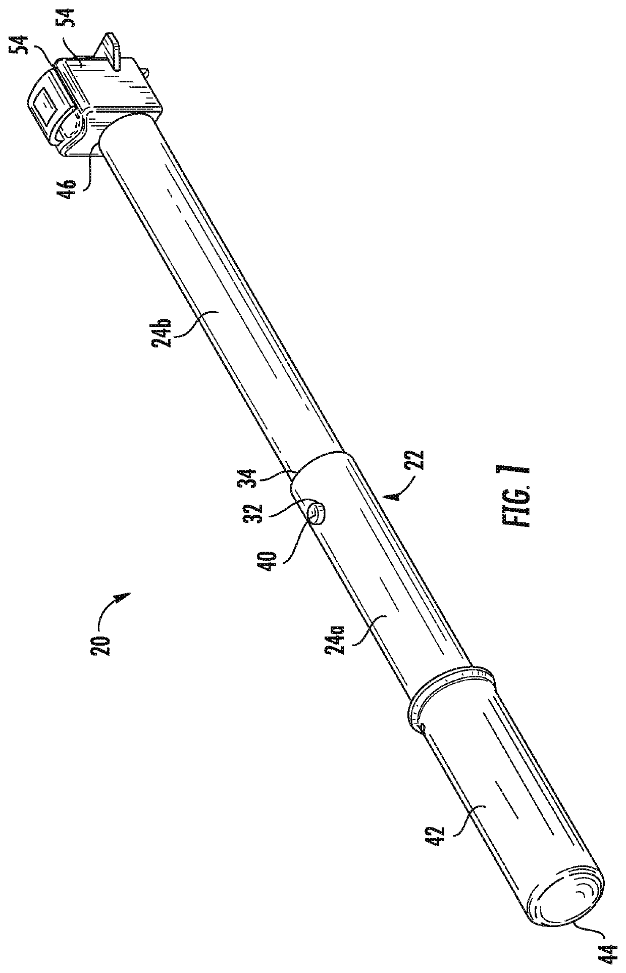
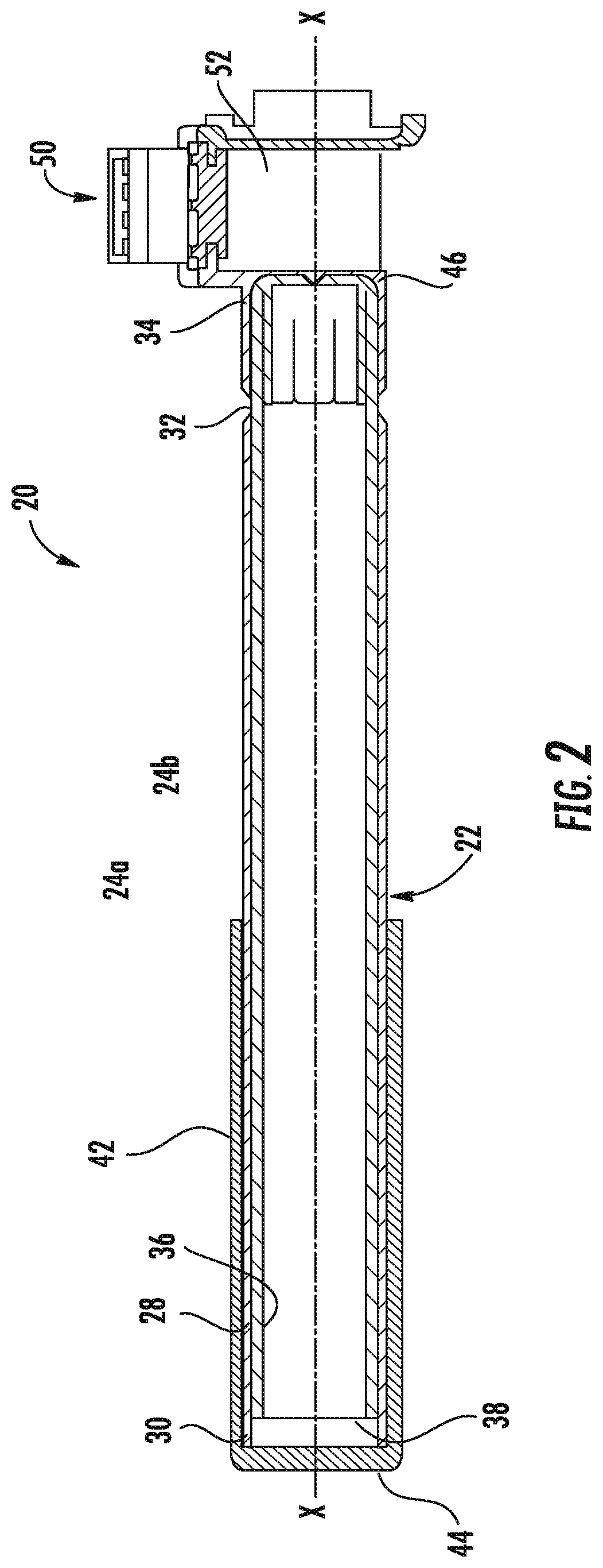
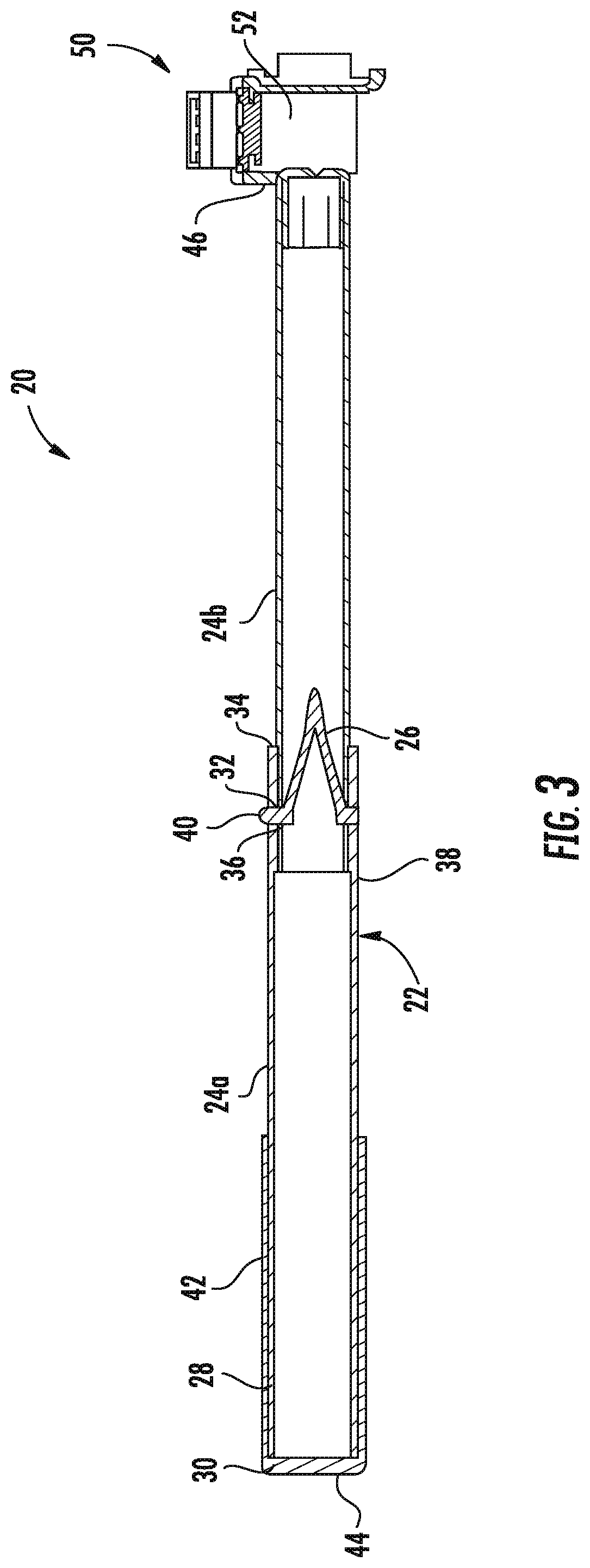
[0034]Referring now to the FIGS., an example of tool 20 commonly referred to as a “hot stick” is illustrated. The tool 20 is configured to allow a user to manipulate a piece of equipment from a selected distance away from a workpiece. For example, in an embodiment, the tool 20 may be suitable for electrical use up to 600 volts per ASTM and CSA standards. Alternatively, the tool may be suitable for electrical use up to 750 or 1000 volts.

[0035]As shown, the tool 20 includes a telescoping arm 22 having a plurality of tubular sections 24 slidable along a longitudinal axis X of the tool 20 to vary the length thereof. In the illustrated, non-limiting embodiment, the arm 22 includes a first tubular section 24a and a second tubular section 24b movable between a retracted position (FIG. 2) and an extended position (FIG. 3). Although an arm22 having only two tubular sections 24a, 24b is illustrated and described herein, it should be understood that an arm 22 having any number of sections 24 i...


PUM


Abstract

A hot stick for manipulating a probe from a position a selected distance away from a workpiece, the tool including an arm, a connector coupled to the arm, the connector including a connector body having a contoured first surface, and a mechanism movable relative to the connector body and configured to cooperate with the first surface of the body to retain a probe.

Description

CROSS-REFERENCE TO RELATED APPLICATIONS[0001]This application claims the benefit of U.S. Provisional Application Ser. No. 62 / 575,109 filed Oct. 20, 2017, which is incorporated herein by reference in its entirety.BACKGROUND[0002]The subject matter disclosed herein relates to person safety equipment, and more specifically, the disclosure relates to a hand held reach tool for use in electrical applications.[0003]Hand-held electrical probes are known in the art for detecting the presence of AC signal potential on a conductor. One type of probe requires direct electrical contact with an uninsulated portion of the conductor. There is a safety risk associated with the contacting type probes due to the possibility that the user may receive a harmful electrical shock.BRIEF DESCRIPTION[0004]According to one embodiment, a hot stick for manipulating a probe from a position a selected distance away from a workpiece, the tool including an arm, a connector coupled to the arm, the connector includi...

Claims


Application Information

Patent Timeline
Patent Type & Authority Patents(United States)
IPC IPC(8): B25B9/00H01H31/00B25G3/20B25G1/12B25G1/04
CPCH01H31/006B25B9/00B25G1/04B25G1/12B25G3/20G01R1/04H01R11/14
Inventor BROWNE, BENJAMIN ALANRODRIGUEZ, ROBERTKEANE, RYAN N.DIX, KEVIN J.BUCKLEY, CRAIG A.
Owner OTIS ELEVATOR CO
Why Eureka
Try Eureka