Check patentability & draft patents in minutes with Patsnap Eureka AI!

Terminal module

a terminal module and module technology, applied in the direction of coupling contact members, coupling device connections, transportation and packaging, etc., can solve the problems of crimping and fixing the guiding bar to the case, the above configuration the component cost of the guiding bar is not an option, so as to reduce the cost of the terminal module

Active Publication Date: 2021-05-11
AUTONETWORKS TECH LTD +2
View PDF6 Cites 1 Cited by
  • Summary
  • Abstract
  • Description
  • Claims
  • Application Information

AI Technical Summary

Benefits of technology

The patent text claims that it explains a way to save money on a terminal module for a high-current use.

Problems solved by technology

However, a conduction failure occurs in such a method, if an external matter adheres between the contact points, a conduction failure occurs.
However, the above configuration is not an option when a large current is used.
However, the component cost of the guiding bar and crimping cost for crimping and fixing the guiding bar to the case would have to be incurred.
Thus, the cost of a terminal module would increase.

Method used


Image

  • Terminal module
  • Terminal module
  • Terminal module

Examples


Embodiment Construction

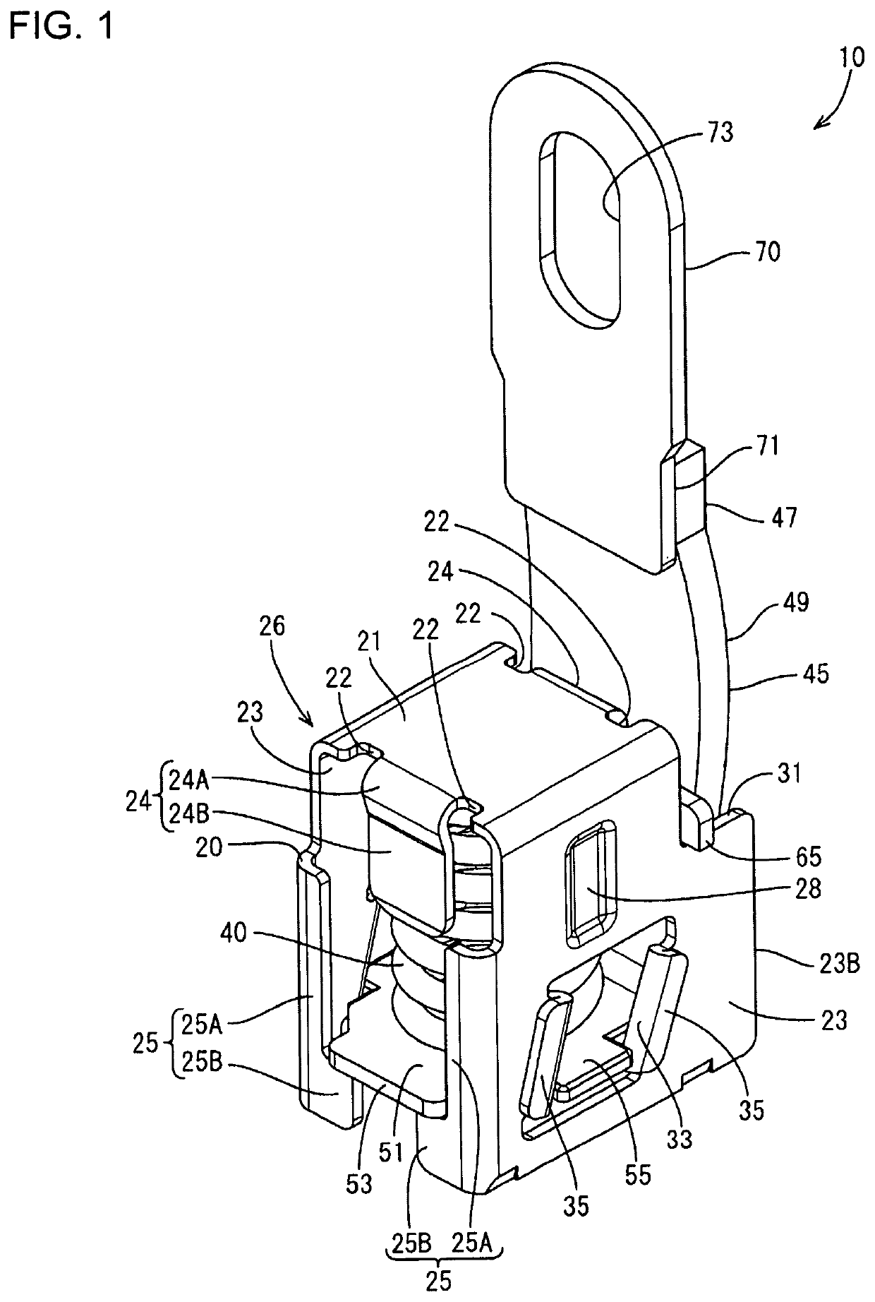
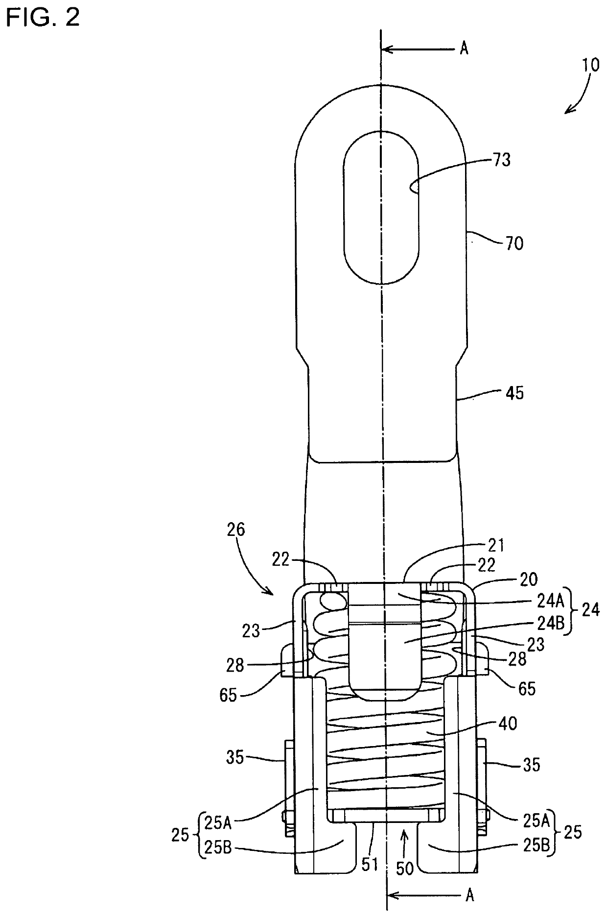
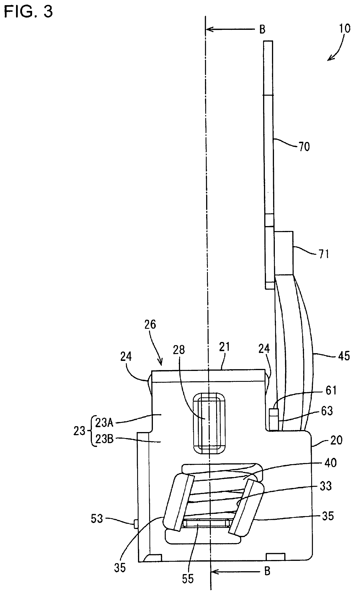
[0022]An embodiment is described with reference to FIGS. 1 to 11. A terminal module 10 of this embodiment is connected electrically to a mating terminal 90 by being butted against the mating terminal 90. In the following description, an upper side in FIG. 10 is referred to as an upper side and a lower side (side of the mating terminal 90) in FIG. 10 is referred to as a lower side. Further, a left side in FIG. 3 is referred to as a front and a right side (side of a braided wire 45) in FIG. 3 is referred to as a rear.

[0023]The terminal module 10 of this embodiment includes, as shown in FIG. 1, a case 20 and a coil spring 40 accommodated in a compressed state inside the case 20. The case 20 includes an electrical contact 50 biased toward an opening 27 of the case 20 by the coil spring 40, and this electrical contact 50 is connected conductively to an external connecting member 70 via the braided wire 45.

[0024]As shown in FIGS. 1 and 2, the case 20 includes a ceiling wall 21, left and r...


PUM


Abstract

A terminal module (10) has a metal case (20) with a ceiling wall (21), a bottom wall (51) facing the ceiling wall (21), opposed side walls (23) extending from the ceiling wall (21) toward the bottom wall (51) and retaining pieces (24). A coil spring (40) is sandwiched between the ceiling wall (21) and the bottom wall (51). The retaining pieces (24) face each other in a direction perpendicular to a facing direction of the side walls (23) and project toward the bottom wall (51) from the periphery of the ceiling wall (21). The side walls (23) and the retaining pieces (24) are disposed alternately on the periphery of the ceiling wall (21). A spring receiving portion (26) formed by the ceiling wall (21), the side walls (23) and the retaining pieces (24) receives an end part of the coil spring (40) on the side of the ceiling wall (21).

Description

BACKGROUNDField of the Invention[0001]This specification relates to a terminal module.Related Art[0002]A method for electrical connection is known by which contact points facing each other butt into contact, for example, in establishing an electrical connection in an automotive vehicle or the like. However, a conduction failure occurs in such a method, if an external matter adheres between the contact points, a conduction failure occurs.[0003]Japanese Unexamined Patent Publication No. 2002-274290 discloses a power supply device that removes external matter from both contact points by sliding the contact points against each other when butting the contact points against each other. Specifically, the power supply device of Japanese Unexamined Patent Publication No. 2002-274290 has a female junction with end plates facing the inside of a case and a coil spring sandwiched and compressed between these end plates. The end plate on a side exposed to the outside has a resilient leaf spring. ...

Claims


Application Information

Patent Timeline
Patent Type & Authority Patents(United States)
IPC IPC(8): H01R13/08H01R13/24H01R13/187H01R4/48
CPCH01R13/08H01R13/2421H01R4/4863H01R13/187B60R16/02H01R11/12H01R4/48H01R13/6315H01R13/24H01R2201/26
Inventor NISHIJIMA, SEIDO
Owner AUTONETWORKS TECH LTD
Features
  • R&D
  • Intellectual Property
  • Life Sciences
  • Materials
  • Tech Scout
  • Unparalleled Data Quality
  • Higher Quality Content
  • 60% Fewer Hallucinations
Learn More