Powder detection device and toner replenishment device
a detection device and toner technology, applied in the direction of instruments, electrographic process devices, optics, etc., can solve the problems of false positives that tell the presence of toners, toner interposed,
- Summary
- Abstract
- Description
- Claims
- Application Information
AI Technical Summary
Problems solved by technology
Method used
Image
Examples
first embodiment
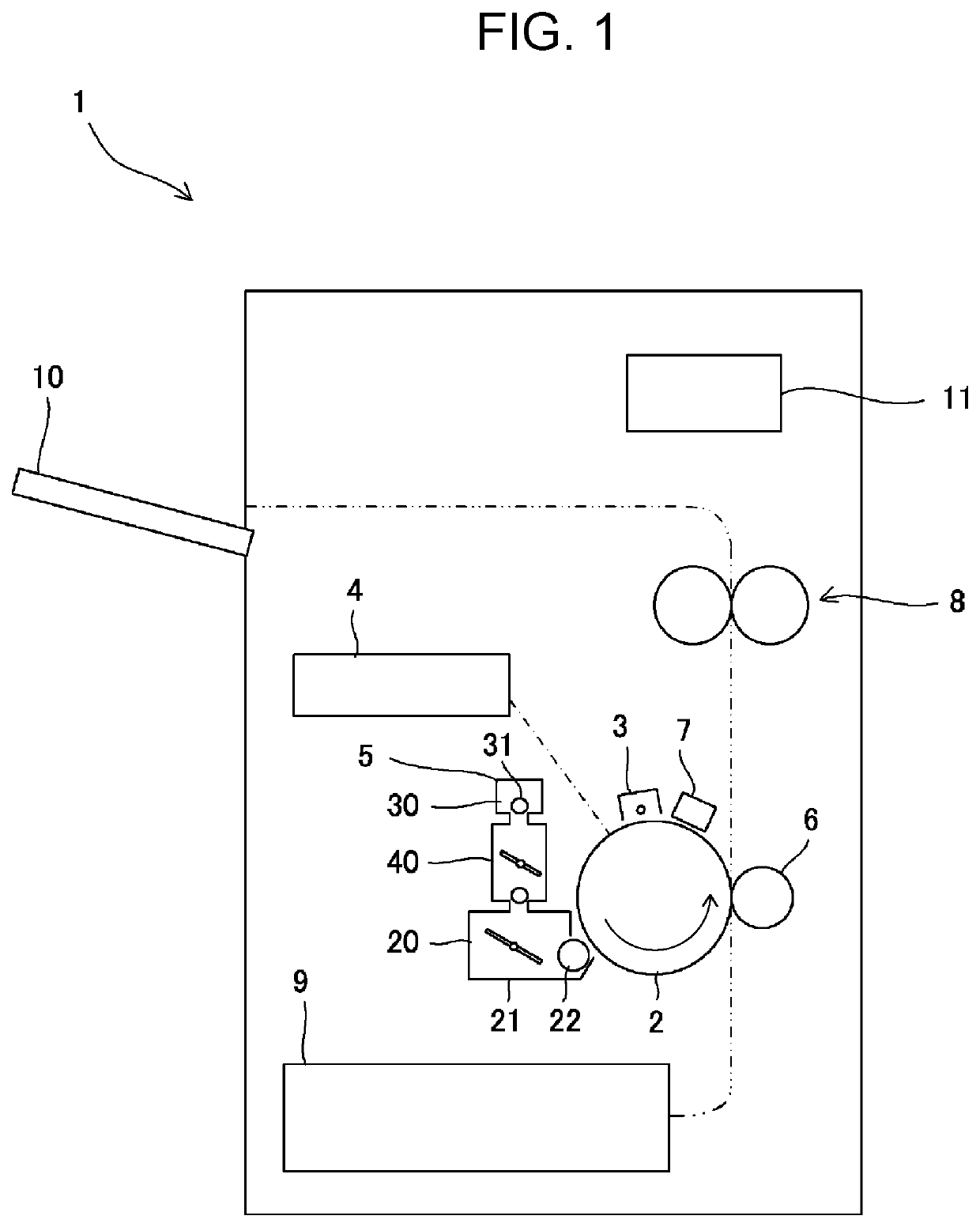
[0021]A powder detection device of the disclosure is embodied as a toner detection device to detect toner that is used in electrophotographic image forming processing, for instance. A toner detection device according to a first embodiment of the disclosure is applied to an image forming apparatus 1.
[0022]As illustrated in FIG. 1, the image forming apparatus 1 includes a photosensitive drum 2, a charging device 3, an exposing device 4, a development device 5, a transfer device 6, a cleaning unit 7, a fixation device 8, a paper feed tray 9, an output tray 10, and a control unit 11.
[0023]The photosensitive drum 2, which is an example of an electrostatic latent image carrier, includes a photosensitive layer on a peripheral surface thereof and rotates in one direction. The charging device 3 charges the peripheral surface of the photosensitive drum 2 at a specified potential. The exposing device 4 forms an electrostatic latent image by exposing the peripheral surface of the photosensitive...
second embodiment
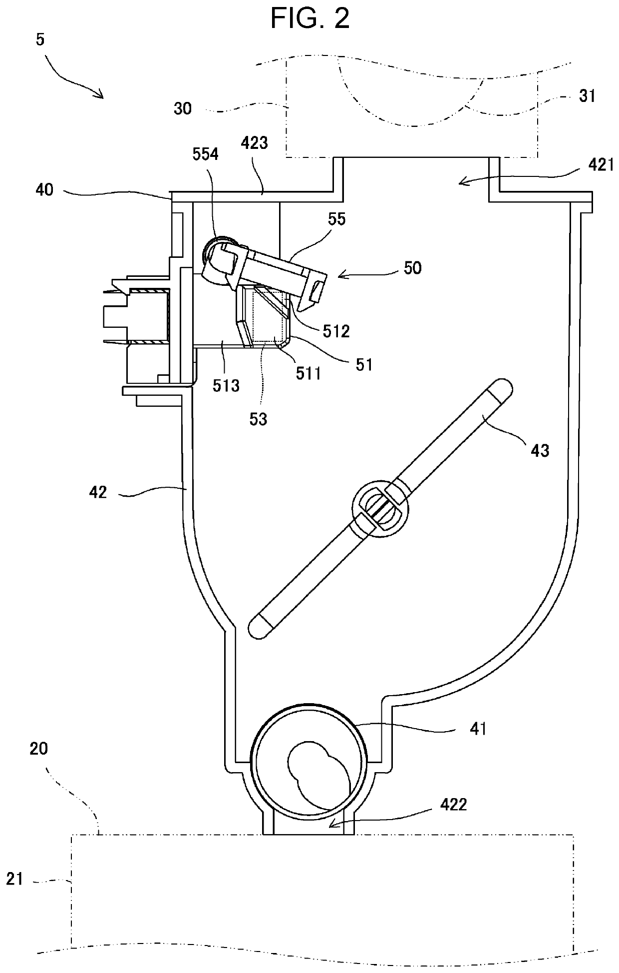
[0057]When the presence or absence of the toner is detected by the optical sensors 53, 54, it is desirable to carry out such processing as follows. The determination of the presence or absence of the toner at the specified elevation in the hopper container 42 is iterated while the toner is supplied from the toner cartridge 30 to the hopper 40 and while the development tank 21 is replenished with the toner from the hopper 40. Besides, the cleaning member 55 and the stirring member 43 continue to rotate while the toner is supplied from the toner cartridge 30 to the hopper 40 and while the development tank 21 is replenished with the toner from the hopper 40.
[0058]As illustrated in FIG. 9, the control unit 11 initially resets a sampling count SC for the output values from the optical sensor 54 (S1). The control unit 11 also resets a light interception count IC that is a count of sampling of the output value from the optical sensor 54 indicating the light interception state (S2). As an i...
third embodiment
[0070]As illustrated in FIGS. 10 and 11, it is desirable to process operations of supplying the toner from the toner cartridge 30 to the hopper 40 as follows. In case where the cleaning member 55 is to be stopped, it is desirable for the control unit 11 to stop the cleaning member 55 after a specified time has elapsed since a transition from a light interception period in which the light path between the optical sensors 53, 54 is intercepted to a transmissive period in which the light path between the optical sensors 53, 54 is transmissive. Specifically, the operations are processed as follows.
[0071]If the control unit 11 determines that the toner is not contained up to the specified elevation in the hopper container 42, the control unit 11 then determines that a start request for toner replenishment from the toner cartridge 30 to the hopper 40 is made (S21) and starts driving the motor 556 for the hopper 40 that rotates the cleaning member 55 and driving a motor that rotates the su...
PUM
 Abstract
Description
Claims
Application Information
 - R&D
- Intellectual Property
- Life Sciences
- Materials
- Tech Scout
- Unparalleled Data Quality
- Higher Quality Content
- 60% Fewer Hallucinations
Browse by: Latest US Patents, China's latest patents, Technical Efficacy Thesaurus, Application Domain, Technology Topic, Popular Technical Reports.
© 2025 PatSnap. All rights reserved.Legal|Privacy policy|Modern Slavery Act Transparency Statement|Sitemap|About US| Contact US: help@patsnap.com


