Check patentability & draft patents in minutes with Patsnap Eureka AI!

Vehicle differential device

a technology of differential case and pinion gear, which is applied in the direction of gearing details, belts/chains/gearrings, gearing details, etc., can solve the problems of limiting the possibility of size reduction of other pinion gears, difficult to generate a large differential limiting force, and imposing large load, so as to increase the man-hours for processing the differential case

Active Publication Date: 2021-06-08
JTEKT CORP
View PDF22 Cites 1 Cited by
  • Summary
  • Abstract
  • Description
  • Claims
  • Application Information

AI Technical Summary

Benefits of technology

[0005]In the differential device described in JP 2009-197976 A, depending on a direction of relative rotation of the right and left side gears, the small diameter gear portion of the one pinion gear receives a radial force toward the right side gear. Therefore, as represented by a reference character 20F shown in FIGS. 2 and 3 of JP 2009-197976 A, a gear support portion needs to be formed in the housing (differential case) such that the gear support portion is interposed between the small diameter gear portion of the one pinion gear and the right side gear. Thus, man-hours for processing the differential case is increased. In addition, the other pinion gear meshes with the small diameter gear portion of the one pinion gear and the right side gear, that is, at two locations, in the circumferential direction. Thus, a large load is imposed on the other pinion gear when transmitting drive force, and this limits the possibility of size reduction of the other pinion gear.
[0007]In view of this, the present disclosure provides a vehicle differential device that can be reduced in size while suppressing an increase in processing man-hours and a decrease in the differential limiting force.
[0009]In the vehicle differential device according to the first aspect of the present disclosure, the vehicle differential device can be reduced in size while suppressing the increase in the processing man-hours and the decrease in the differential limiting force.

Problems solved by technology

Thus, a large load is imposed on the other pinion gear when transmitting drive force, and this limits the possibility of size reduction of the other pinion gear.
Further, if diameters of the right and left side gears are reduced in order to reduce the size of the device, frictional sliding diameters between the right and left side gears and the washers are reduced, making it difficult to generate a large differential limiting force.

Method used


Image

  • Vehicle differential device
  • Vehicle differential device
  • Vehicle differential device

Examples


embodiment

[0020]An embodiment of the present disclosure will be described with reference to FIGS. 1 to 4. Note that the embodiment described below is represented as a specific example suitable for implementing the present disclosure. Although some parts exemplify various technical matters that are technically preferable, the technical scope of the present disclosure is not limited to the specific examples.

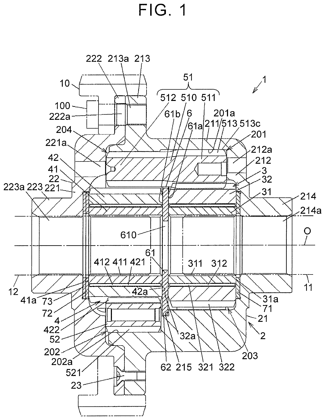
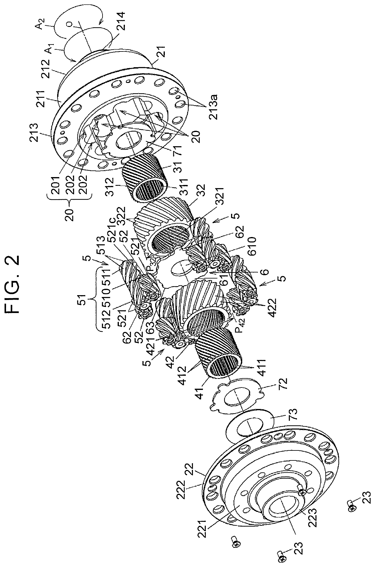
[0021]FIG. 1 is a sectional view of a differential device according to the embodiment of the present disclosure. FIG. 2 is an exploded perspective view of the differential device.

[0022]A differential device 1 that is mounted on a vehicle is used to distribute a drive force (torque), which is input from a ring gear 10, from a driving source of the vehicle, such as an engine, to the first and second output shafts 11 and 12 while allowing a differential rotation thereof. In FIG. 1, the ring gear 10 and the first and second output shafts 11 and 12 are indicated by virtual lines (long dashed doub...


PUM


Abstract

A vehicle differential device includes a plurality of pinion gear sets. Each of the pinion gear sets includes a first pinion gear configured to mesh with a first outer helical gear and a plurality of second pinion gears configured to mesh with a second outer helical gear. The first pinion gear integrally includes an axially one end side gear portion configured to mesh with the first outer helical gear and an axially other end side gear portion configured to mesh with the second pinion gears. The second pinion gears are configured to mesh with the second outer helical gear at positions separated from each other in a circumferential direction of the second outer helical gear, and the axially other end side gear portion of the first pinion gear is configured to mesh with the second pinion gears at positions radially outward of the second outer helical gear.

Description

INCORPORATION BY REFERENCE[0001]The disclosure of Japanese Patent Application No. 2019-050718 filed on Mar. 19, 2019 including the specification, drawings and abstract is incorporated herein by reference in its entirety.BACKGROUND1. Technical Field[0002]The present disclosure relates to a vehicle differential device that can distribute an input drive force to a pair of output shafts while allowing a differential rotation thereof.2. Description of Related Art[0003]The vehicle differential device that can distribute the input drive force to right and left drive shafts while allowing the differential rotation thereof includes right and left side gears, a plurality of pinion gear sets, a housing, and washers. The right and left side gears rotate integrally with the right and left drive shafts, respectively. Each of the pinion gear sets includes a pair of pinion gears disposed in parallel to the right and left side gears such that the pinion gears mesh with each other. The housing holds ...

Claims


Application Information

Patent Timeline
Patent Type & Authority Patents(United States)
IPC IPC(8): F16H48/06F16H57/037F16H48/38
CPCF16H48/06F16H48/38F16H57/037F16H48/28F16H48/285F16H48/40F16H2048/385
Inventor JIN, HEYOSHIHAMA, TOMOKIASAMI, KENJILI, SONGJIE
Owner JTEKT CORP
Features
  • R&D
  • Intellectual Property
  • Life Sciences
  • Materials
  • Tech Scout
  • Unparalleled Data Quality
  • Higher Quality Content
  • 60% Fewer Hallucinations
Learn More