
Floating connector

a technology of floating connectors and connectors, applied in the direction of coupling contact members, incorrect coupling prevention, electrical equipment, etc., can solve problems such as difficulty in achieving

Active Publication Date: 2021-06-08
ODU GMBH & CO
View PDF28 Cites 6 Cited by
  • Summary
  • Abstract
  • Description
  • Claims
  • Application Information

AI Technical Summary

Benefits of technology

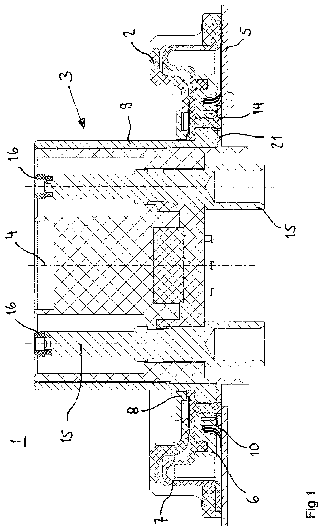
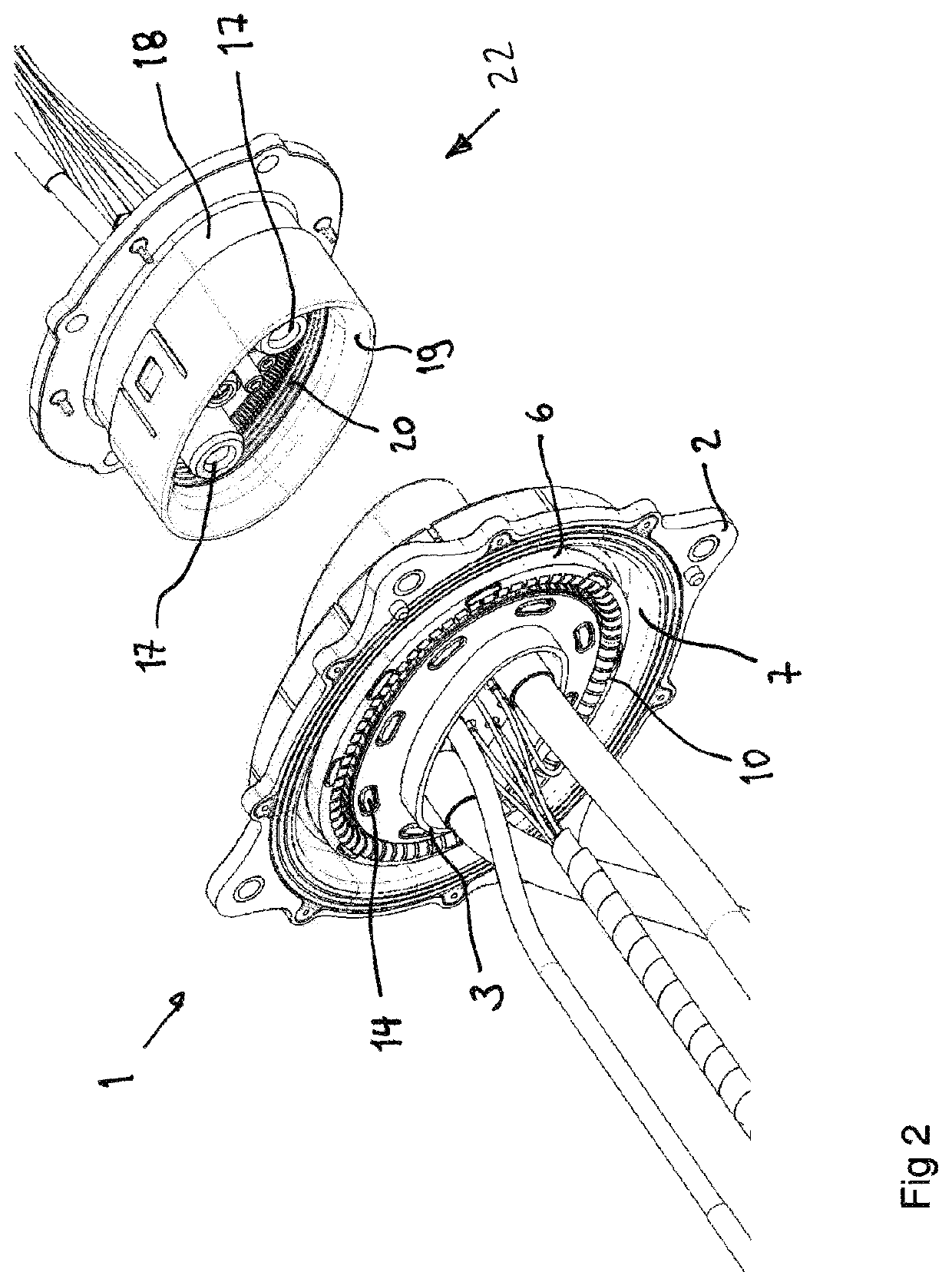
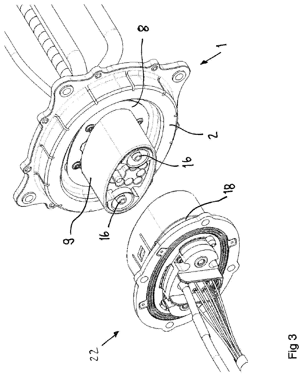
[0013]It is an achievable advantage of this aspect of the invention that the essentially oval outer surface of the contact housing can cooperate with the aperture to provide a limit stop for the relative movement of the contact housing and the frame. Thus the angular movement of the contact housing inside the aperture can be sterically constrained to limit the rotation of the contact housing relatively to the frame to a pre-defined angular range. It is another achievable advantage of the essentially oval outer surface of the contact housing that it can provide for or assist a rotational alignment of the contact housing and a mating connector.
[0045]Preferably, the rim of the opening of the contact enclosure comprises a lead-in chamfer. In an alternative embodiment of the invention, the lead-in chamfer is provided at the rim of the opening of the floating connector's contact housing. The lead-in chamfer on one of the elements contact enclosure and the contact housing can co-operate with the rim of the other element in order to align the contact housing with the contact enclosure and, consequently, the mating connector. The preferred lead-in chamfer has an essentially oval shape. The preferred edge co-operating with the lead-in chamfer preferably has an essentially oval shape. The oval shape advantageously can provide for or assist a rotational alignment of the contact housing and the contact enclosure and, consequently, the mating connector.

Problems solved by technology

Such difficulties can, for example, arise if alignment requires a precise positioning of the battery, which is difficult to achieve due to the battery's mass and / or its location in the vehicle.

Method used


Image

  • Floating connector
  • Floating connector
  • Floating connector

Examples


Embodiment Construction

[0023]Preferred features of the invention, which may be applied alone or in combination, are discussed in the following and in the dependent claims.

[0024]In a preferred embodiment of the invention, the contact housing is rotatable about an axis that extends perpendicularly to the surface defined by the aperture. It is an achievable advantage of this embodiment of the invention that the floating connector can compensate for a certain degree of angular misalignment between the floating connector and a mating connector. Preferably, the aperture has a non-circular shape, for example an essentially oval shape. The preferred contact housing has an essentially ovally cylindrical outer surface with the cylinder's axis extending perpendicularly to the surface defined by the aperture.

[0025]Preferably, the shape and size of the aperture and the contact housing's perimeter in the surface of the aperture are chosen to limit to a pre-defined angular range the rotation of the contact housing relat...


PUM


Abstract

An improved floating connector can be employed for, among other things, connecting a traction battery to the drive of an electrically-driven vehicle. The self-aligning floating connector can be used to mate connectors of the battery and the electric drive despite misalignment. The floating connector has a frame and a contact housing movable inside an aperture of the frame. The contact housing is rotatable about an axis that extends perpendicularly to the surface defined by the aperture. The essentially oval outer surface of the contact housing can cooperate with the aperture to provide a limit stop for the relative movement of the contact housing and the frame. The angular movement of the contact housing inside the aperture can be sterically constrained to limit the rotation of the contact housing relative to the frame to a pre-defined angular range. A system with a floating connector and a mating connector is also disclosed.

Description

CROSS-REFERENCE TO RELATED APPLICATIONS[0001]This application claims priority to German Patent Application DE 20 2018 105 926.2 U1, filed on Oct. 16, 2018, the disclosure of which is incorporated in this application in its entirety.FIELD OF THE INVENTION[0002]The invention relates to a floating connector comprising a frame and a contact housing that is movable inside an aperture of the frame in a surface defined by the aperture. The invention further relates to a system comprising a floating connector and a mating connector that can connect with the floating connector to establish an electrical contact.BACKGROUND OF THE INVENTION[0003]From U.S. Pat. No. 4,030,797: A an electrical connector is known that includes a housing with a tube-like plug shell mounted inside the housing in a manner to translate in either or both of two different directions, to rotate about the housing axis, and to tilt about the housing axis. The plug shell has a flared end portion to receive a receptacle. The...

Claims


Application Information

Patent Timeline
Patent Type & Authority Patents(United States)
IPC IPC(8): H01R13/64H01R13/631H01R13/08H01R13/502
CPCH01R13/6315H01R13/08H01R13/502H01R13/74H01R2201/26
Inventor MITTER, ALFREDSAUCEDO, JORGE
Owner ODU GMBH & CO
Learn More