Image encoding apparatus, control method thereof, and non-transitory computer-readable storage medium

a technology of image encoding and control method, applied in the direction of pictoral communication, digital video signal modification, electric apparatus, etc., can solve the problems of affecting image quality, value reaching the upper limit of the possible pixel value range, and difficulty in encoding input images, etc., to achieve the effect of suppressing color shi

Active Publication Date: 2021-06-08
CANON KK
View PDF6 Cites 0 Cited by
  • Summary
  • Abstract
  • Description
  • Claims
  • Application Information

AI Technical Summary

Benefits of technology

[0005]Having been achieved in light of the aforementioned issue, the present invention provides a technique for suppressing color shifts caused by quantization parameters used to encode RAW image data.

Problems solved by technology

However, depending on the shooting conditions, compressing an image may harm the image quality.
However, the following issue arises when using the stated past technique with RAW images, in which the data changes depending on the shooting conditions, the level of difficulty of encoding the input image, and so on.
That is, applying white balancing can, depending on the color component, result in the value reaching the upper limit of the possible pixel value range, which makes it necessary to clip the value.

Method used


Image

  • Image encoding apparatus, control method thereof, and non-transitory computer-readable storage medium
  • Image encoding apparatus, control method thereof, and non-transitory computer-readable storage medium
  • Image encoding apparatus, control method thereof, and non-transitory computer-readable storage medium

Examples


first embodiment

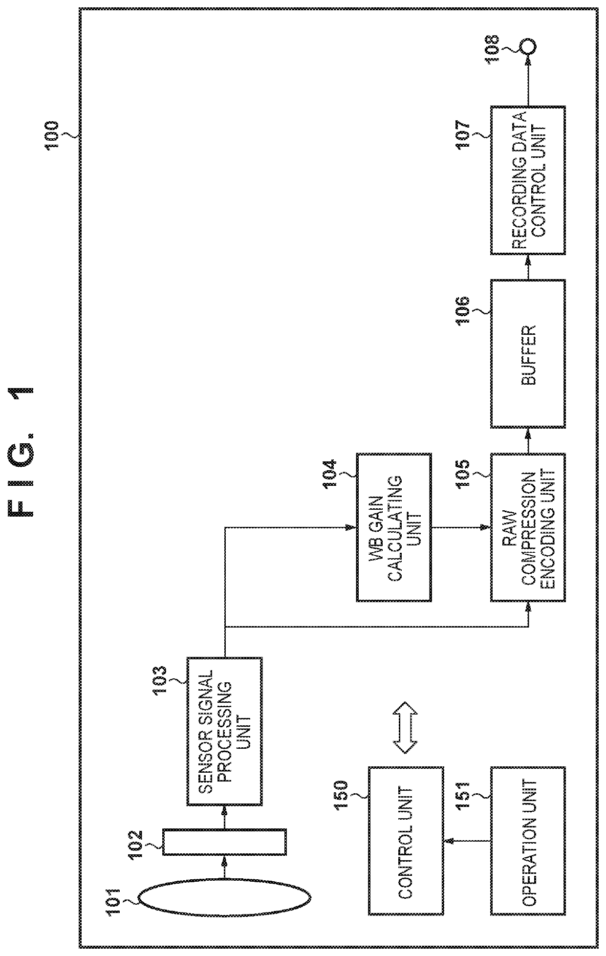
[0027]FIG. 1 is a block diagram illustrating the main components of an image capturing apparatus 100) according to a first embodiment. The image capturing apparatus 100 includes an imaging optical unit 101, an imaging sensor 102, a sensor signal processing unit 103, a WB gain calculating unit 104, a RAW compression encoding unit 105, a buffer 106, a recording data control unit 107, a control unit 150, and an operation unit 151.

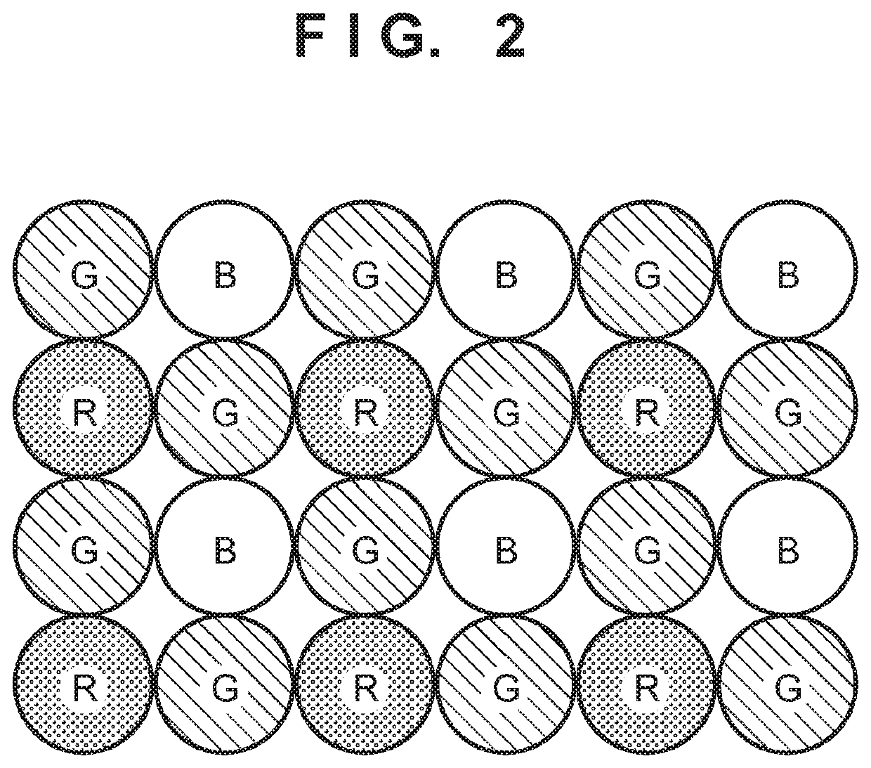
[0028]With the configuration illustrated here, when a user inputs an instruction to start shooting operations through the operation unit 151, an optical image of a subject of which an image is to be captured is input through the imaging optical unit 101 and formed on the imaging sensor 102. The imaging sensor 102 converts the intensity of light, which passes through red (R), green (G), and blue (B) color filters arranged on a pixel-by-pixel basis, into electrical signals. Note that the imaging sensor 102 is assumed to capture images at a speed of, for example,...

second embodiment

[0082]A second embodiment will now be described. The apparatus configuration according to the present second embodiment is the same as that illustrated in FIG. 1 and described in the first embodiment. However, the processing carried out by the RAW compression encoding unit 105, and the data recorded to a recording medium group 107, according to the present second embodiment are different from in the first embodiment, and will therefore be described in detail.

[0083]FIG. 12 is a block diagram illustrating the configuration of the RAW compression encoding unit 105 according to the present second embodiment. Processing units that are the same as those illustrated in FIG. 3 and described earlier in the first embodiment are given the same reference signs, and will not be described. FIG. 12 differs from FIG. 3 in that a plane transform unit 1213 has been added, and the WB control unit 311 of FIG. 3 has been replaced with a second WB control unit 1214.

[0084]Processing performed by the RAW c...

third embodiment

[0112]A third embodiment will now be described. The apparatus configuration according to the present third embodiment is the same as that illustrated in FIG. 1 and described in the first embodiment.

[0113]When multiplying the gain values with the color component values during the white balancing, a value will be clipped at the upper limit value if it reaches that upper limit value. For example, when one component is 8 bits, the upper limit value is 255. As such, the lower the gain value is, the better. This is because even if a complete white balancing is not applied, an intermediate gain value can be multiplied within the range that guarantees the image quality, and the image may then be encoded. The remaining gain value may then be multiplied when the image is developed. The following will therefore describe an example in which an intermediate gain value is multiplied.

[0114]FIG. 15 is a table illustrating a relationship between color temperature and gain value for R and B (the tabl...


PUM


Abstract

This invention suppresses color shifts caused by quantization parameters used when encoding RAW image. An apparatus comprises a calculator which finds a color temperature of RAW image of a target frame, and calculates a gain value for each of color components in order to apply white balancing to the RAW image, a generator which generates a plurality of planes, each plane constituted by data of a single color component, from the RAW image, an adjusting unit which adjusts the white balance of each plane on the basis of the calculated gain, an encoder which encodes each plane by frequency-transforming, quantizing, and encoding each plane, and a controller which switches between encoding the plurality of planes generated by the generating unit or encoding the plurality of planes adjusted by the adjusting unit, on the basis of quantization parameters.

Description

BACKGROUND OF THE INVENTIONField of the Invention[0001]The present invention relates to RAW image data encoding technology.Description of the Related Art[0002]Image capturing apparatuses such as digital cameras or electronic devices having image capturing functions carry out what is known as developing processing. In this processing, raw image information (a RAW image) obtained by an image sensor is subjected to debayering (demosaicing) and converted into signals constituted by luma and chroma components, and each signal is then subjected to noise removal, optical distortion correction, image optimization, and the like. The developed luma and chroma signals are then compressed, encoded, and recorded into a recording medium.[0003]There are also image recording apparatuses capable of recording RAW images. A RAW image is a type of data that keeps correction, degradation, and the like to a minimum. Advanced users therefore prefer to use RAW images for editing after shooting. However, RA...

Claims


Application Information

Patent Timeline
Patent Type & Authority Patents(United States)
IPC IPC(8): H04N7/12H04N19/13H04N19/625H04N19/182H04N19/154H04N19/147H04N19/186H04N19/117
CPCH04N19/13H04N19/117H04N19/147H04N19/154H04N19/182H04N19/186H04N19/625H04N19/85
Inventor OISHI, AKIHIRO
Owner CANON KK
Why Eureka
Try Eureka