Additively manufactured control valve flow element

a technology of flow element and additive manufacturing, which is applied in the direction of valve details, valve arrangements, valve members for absorbing fluid energy, etc., can solve the problems of reducing the effectiveness of the control device in achieving the desired energy loss, affecting the flow characteristics of the valve, and affecting the effect of the flow

Active Publication Date: 2021-07-13
CONTROL COMPONENTS INC
View PDF9 Cites 0 Cited by
  • Summary
  • Abstract
  • Description
  • Claims
  • Application Information

AI Technical Summary

Benefits of technology

[0006]In order to address the problems noted above, control devices have been developed which result in energy losses by sub-dividing the flow into a plurality of small passageways with abrupt turns creating friction and pressure drop in the fluid. The passageways may be provided in an annular stack of discs, which may be mounted in the fluid passage of a valve housing. A plug may be moveable within the annular structure to control the number of passageways in the stack through which fluid can flow.
[0008]Accordingly, there is a need in the art for an improved control device which addresses the issues of cavitation and vibration that may occur in conventional control devices, while also providing a lightweight design. Various aspects of the present disclosure address this particular need, as will be discussed in more detail below.

Problems solved by technology

However, the extreme conditions of the fluid flowing through such control devices may result in erosion in the control device due to cavitation, which may refer to high speed implosion of fluid against the components of the control device.
Erosion of the control device may reduce the effectiveness in its ability to attain the desired energy loss or high pressure drops.
In addition to the erosion issues, the high pressure and high velocity flow of the fluid may also cause flow characteristics within the valve to become unpredictable and erratic.
The extreme flow characteristics may also generate unwanted noise, which in some instances may result in sound pressure levels of 110 to 170 dB three feet from the valve exit.
Sound levels of this magnitude may be hazardous to those located near the fluid flow and may result in complaints from local residents.
Although such control devices may be useful in achieving a desired energy loss, there may be limitations associated with such conventional control devices.
One particular deficiency is that the configuration of the control device may allow flow separation of a fluid flowing therethrough relative to an adjacent solid boundary under certain fluid pressure conditions.
Flow separation may produce vibrational energy, which may give rise to cavitation and noise.
Another drawback common in conventional control devices is that the components may be heavy, and thus, may be associated with large energy demands during operation.

Method used


Image

  • Additively manufactured control valve flow element
  • Additively manufactured control valve flow element
  • Additively manufactured control valve flow element

Examples


Embodiment Construction

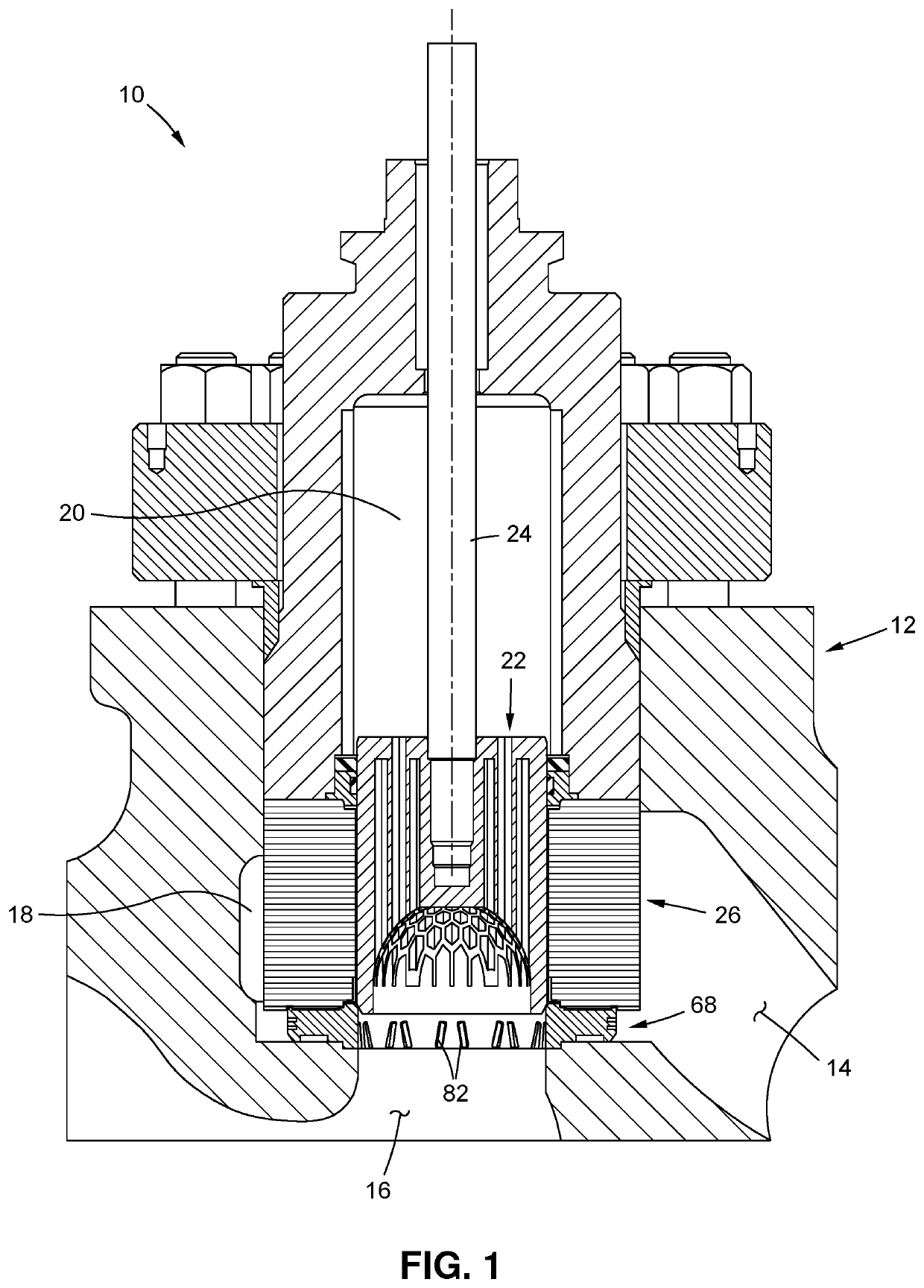
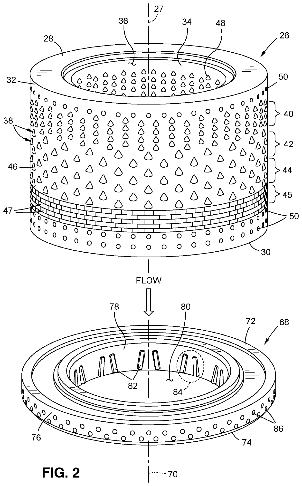
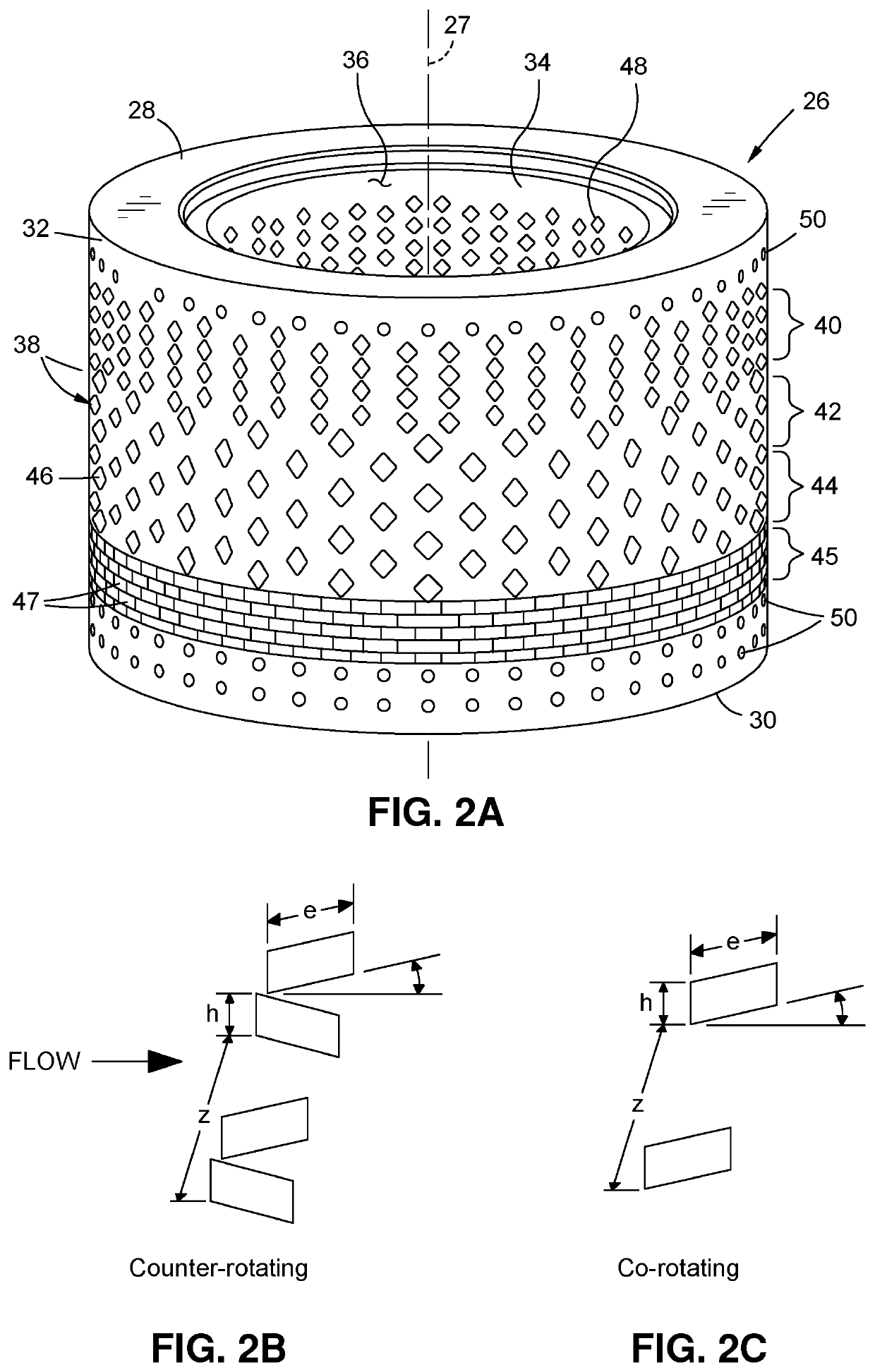
[0026]Referring now to the drawings, wherein the showings are for purposes of illustrating preferred embodiments of the present disclosure only, and are not for purposes of limiting the same, there is depicted a control valve 10 specifically configured and adapted to impart desired flow characteristics to the fluid flowing therethrough, as well as to achieve desired thermal management characteristics of the control valve 10 using lightweight components. More specifically, the control valve 10 may include vortex generators extending into the fluid flow to impart vortices therein so as minimize flow separation from a solid boundary so as to minimizes vibration and noise within the system. The control valve 10 may additionally include thermal management holes to help in reducing the accumulation of heat within the control valve 10. Furthermore, portions of the control valve 10 may be formed from a honeycomb structure to provide a lightweight design without compromising strength. In thi...


PUM


Abstract

A valve for regulating the flow of a fluid includes a housing defining a fluid inlet and a fluid outlet. A flow control element is disposed within the housing and is configured to dissipate energy in a fluid flowing therethrough from the fluid inlet to the fluid outlet. A valve seat is positioned within the housing and includes a plurality of vortex generators which induce vortices in the fluid as the fluid flows through the valve seat. A plug is disposed within the housing and is moveable relative thereto between closed and open positions. The plug moves away from the valve seat as the plug moves from the closed position toward the open position such that fluid flow through the flow control element and the valve seat increases as the plug is moved from the closed position toward the open position.

Description

CROSS-REFERENCE TO RELATED APPLICATIONS[0001]Not ApplicableSTATEMENT RE: FEDERALLY SPONSORED RESEARCH / DEVELOPMENT[0002]Not ApplicableBACKGROUND1. Technical Field[0003]The present disclosure relates generally to a fluid control valve, and more specifically to a fluid control valve formed via additive manufacturing, and having attributes which aid in thermal management, as well as providing strength using a lightweight design.2. Description of the Related Art[0004]The handling of flowing fluids at high pressure may entail the use of control devices to attain energy loss or high pressure drops. However, the extreme conditions of the fluid flowing through such control devices may result in erosion in the control device due to cavitation, which may refer to high speed implosion of fluid against the components of the control device. Erosion of the control device may reduce the effectiveness in its ability to attain the desired energy loss or high pressure drops.[0005]In addition to the er...

Claims


Application Information

Patent Timeline
Patent Type & Authority Patents(United States)
IPC IPC(8): F16K47/08
CPCF16K47/08F16K47/04F16K39/022F16K3/246
Inventor SAMY, SEKHARAHMED, UZAIR
Owner CONTROL COMPONENTS INC
Why Eureka
Try Eureka