Gas appliance, gas valve and control method thereof

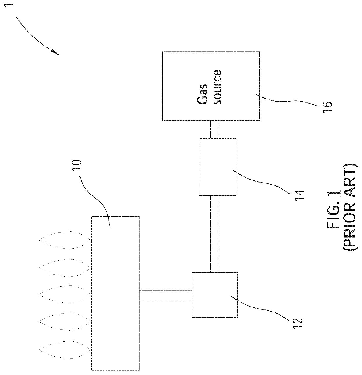
a gas valve and gas appliance technology, applied in the direction of combustion process, combustion regulation, fuel supply regulation, etc., can solve the problems of unstable pressure output of the pressure regulator b>14/b>, affecting the combustion efficiency of the burner, and gas flow rate, so as to reduce the manufacturing cost of the gas appliance, the effect of accurately and quickly sensed, and accurate and rapid control of gas flow ra

Active Publication Date: 2021-07-13
GRAND MATE
View PDF24 Cites 1 Cited by
  • Summary
  • Abstract
  • Description
  • Claims
  • Application Information

AI Technical Summary

Benefits of technology

[0009]The advantage of the present invention is that a variation of the gas flow rate could be sensed accurately and rapidly by disposing the hot film anemometer in the outlet passage, whereby to control the stepper motor and stabilize the gas flow rate passing through the gas valve without disposing the pressure regulator. In this way, the gas flow rate could be controlled more accurately and the manufacturing cost of the gas appliance could be reduced.
is that a variation of the gas flow rate could be sensed accurately and rapidly by disposing the hot film anemometer in the outlet passage, whereby to control the stepper motor and stabilize the gas flow rate passing through the gas valve without disposing the pressure regulator. In this way, the gas flow rate could be controlled more accurately and the manufacturing cost of the gas appliance could be reduced.

Problems solved by technology

However, when the pressure output from the gas source 16 is smaller than a certain pressure, the pressure output from the pressure regulator 14 would be unstable.
Since the gas valve 12 is adapted to regulate the gas flow rate by changing an opening degree of an opening, the gas flow rate would be unstable when the pressure supplying to the gas valve 12 is unstable, thereby affecting the combustion efficiency of the burner 10.

Method used


Image

  • Gas appliance, gas valve and control method thereof
  • Gas appliance, gas valve and control method thereof
  • Gas appliance, gas valve and control method thereof

Examples


Embodiment Construction

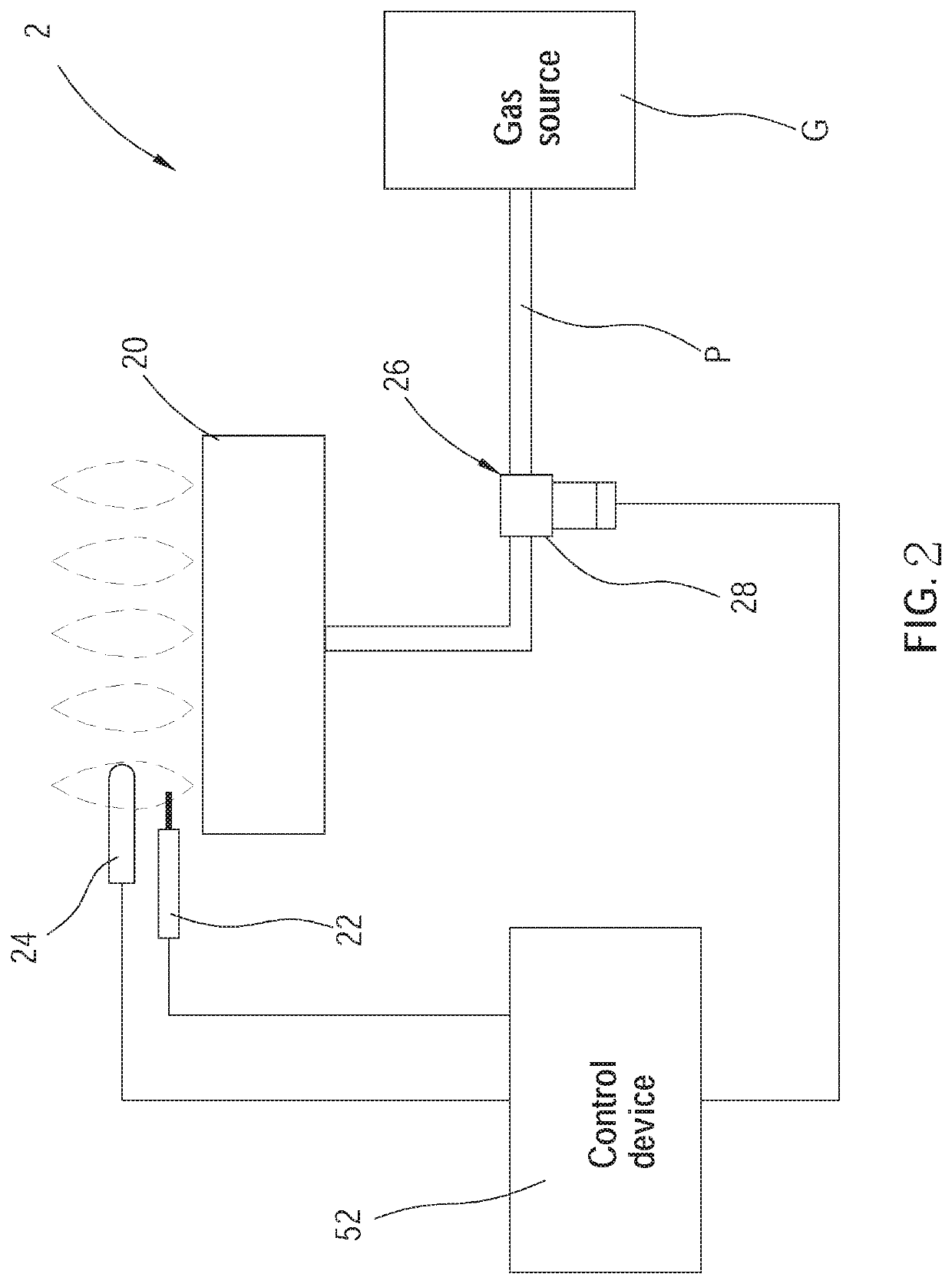
[0022]The following illustrative embodiments and drawings are provided to illustrate the disclosure of the present invention, these and other advantages and effects can be clearly understood by persons skilled in the art after reading the disclosure of this specification. As shown in FIG. 2 to FIG. 5, a gas appliance 2 of a first embodiment according to the present invention includes a burner 20, an ignitor 22, a flame detector 24, a gas valve 26, and a control device 52. In this embodiment, the gas appliance 2 could be a gas heating device such as a gas stove, a fireplace, or a water heater for example.

[0023]The burner 20 is adapted to burn gas to generate flames. The ignitor 22 is disposed adjacent to the burner 20 and is controllable to generate sparks with respect to the burner 20 so as to ignite the gas output from the burner 20. The flame detector 24 is disposed adjacent to the burner 20 to detect the flames. The flame detector 24 could be a thermocouple or a flame sensor as a...


PUM


Abstract

A gas appliance includes a burner, a gas valve, and a control device, wherein the gas valve includes a valve body, a flow regulator, a hot film anemometer, and a stepper motor. The valve body communicates with the burner and a gas source. The flow regulator is driven by the stepper motor to change a gas flow rate supplying to the burner. The hot film anemometer is disposed in the valve body and includes a probe exposed to the outlet passage. The control device executes a control method for the gas valve: sensing the gas flow rate in the outlet passage with the hot film anemometer; comparing the gas flow rate sensed by the hot film anemometer with a predetermined gas flow rate, and controlling the stepper motor to drive the flow regulator based on the comparison result, whereby to stabilize the gas flow rate.

Description

BACKGROUND OF THE INVENTIONTechnical Field[0001]The present invention is related to a gas appliance, and more particularly to a gas appliance, a gas valve, and a control method thereof, which could stabilize a gas flow rate.Description of Related Art[0002]Gas appliances are usually utilized as heating devices. As comparing to electro-thermal heating devices, the gas appliances provide more heat energy by burning gas. In addition, the gas appliances also have a heating time and a response time which are faster than the electro-thermal heating devices.[0003]Referring to FIG. 1, a conventional gas appliance 1 includes a burner 10, a gas valve 12, and a pressure regulator 14, wherein the burner 10 is adapted to burn gas to generate flames; the gas valve 12 communicates with the burner 10 and is adapted to regulate a gas flow rate supplying to the burner 10 manually or automatically; one end of the pressure regulator 14 is connected to the gas valve 12, and another end of the pressure re...

Claims


Application Information

Patent Timeline
Patent Type & Authority Patents(United States)
IPC IPC(8): F23N5/18F23N1/02F23N5/02F23N1/00
CPCF23N5/184F23N1/005F23N1/02F23N5/022F23N5/18F23N2005/185F23N2225/14F23N2235/10F23N2235/16F23N2235/24
Inventor HUANG, CHUNG-CHINHUANG, CHIN-YINGHUANG, HSIN-MINGHUANG, HSING-HSIUNGYEH, YEN-JEN
Owner GRAND MATE
Why Eureka
Try Eureka