Motor vehicle handle

Active Publication Date: 2021-07-20
HUF HULSBECK & FURST GMBH & CO KG
View PDF16 Cites 0 Cited by
  • Summary
  • Abstract
  • Description
  • Claims
  • Application Information

AI Technical Summary

Benefits of technology

[0006]The invention shall provide a motor vehicle actuation device that is distinguished by a functional structure and has a compact and inexpensive construction. In accordance with the invention, the functional element is disposed in its operating position once the control element is located between the initial actuation position and the final actuation position. The control element, moved by the drive device, consequently continues to move, regardless of whether the functional element is already in its operating position and retained there by the control element. In this manner, the functional element can be positioned precisely, even if the drive device is not yet deactivated. This is beneficial, particularly with electrically operated drive devices, because there is always a certain amount of lag in the gearing, which caused major problems for precise positioning of the functional element in the prior art, because the control element did not always ensure the desired, and in particular identical, movement or deflection of the functional element, due to the gearing lag of the control element. This disadvantage is resolved with the invention, because the functional element remains in its operating position, even when the control element continues to move. The area between the initial actuation position to the final actuation position thus corresponds to an area in which the control element continues to move, but this movement does not cause further movement of the functional element away from of the operating position. In accordance with the invention, a lag of the gearing in the drive device is thus allowed for, wherein the gearing lag exerts no influence on the position of the functional element. Moreover, stops are not needed in the motor vehicle actuation device according to the invention for stopping the movement of the control element or the functional element, when the functional element has reached its desired operating position. Consequently, the noises caused by the stop, which have an adverse effect on the satisfaction of the user with the performance of the device, are eliminated. Stops for limiting movement are thus made superfluous by the invention, such that components can be eliminated, and production costs reduced. Because the motor vehicle actuation device according to the invention does not need any stops for delimiting movement, the drive device also does not have the problem caused by blocking the current, such that a driver stage of the drive device does not become overheated, which would otherwise result a reduction in the service life due to overload, or could even lead to damage to the drive device.
[0007]The design of the invention provides that the control element has a drive shaft in a drive connection with the drive device, on which an actuation projection is formed, extending radially away from the drive shaft, which interacts with the functional element when the control element is moved into the initial actuation position, and forces the functional element out of the standby position into the operating position. The actuation projection takes the form of a cam, for example, wherein the cam has a base diameter that corresponds to the diameter of the drive shaft, and a cam lift for the interaction with the functional element, which is greater than the base diameter. The actuation projection is thus formed as a section of the drive shaft in the form of an irregular circumference, and represents a structurally inexpensive option.
[0008]It is particularly advantageous when the actuation projection is formed with two radius line sections and an arc section, seen in an axial perspective, wherein the control element moves from its home position to the initial actuation position via an engagement position when the drive device is activated, wherein the control element moves from its home position to the initial actuation position via an engagement position when the drive device is activated, wherein the actuation projection is disposed at a distance to contact point formed on the functional element offset to the rotational axis, without coming in contact therewith, in the home position, and wherein one of the two radius line sections of the actuation projection bears on the contact point formed on the functional element offset to the rotational axis in the engagement position. The arc-shaped design of the actuation projection of the control element offers a structurally clever option for continuously moving the functional element from its standby position toward its operating position with the help of the radius line section.
[0012]To implement the emergency stop property of the trigger element, it is advantageous when the trigger projection and the trigger element extend radially from the drive shaft with identical radii, wherein the trigger projection and the trigger element are each arc-shaped, with a respective arc, and wherein the arc of the trigger projection is longer than the arc of the trigger element.
[0013]For a compact construction, it is advantageous in the design of the invention, when the arc of the trigger element is disposed such that it lies along its circumference within the arc of the trigger projection when seen from the side.

Problems solved by technology

This is beneficial, particularly with electrically operated drive devices, because there is always a certain amount of lag in the gearing, which caused major problems for precise positioning of the functional element in the prior art, because the control element did not always ensure the desired, and in particular identical, movement or deflection of the functional element, due to the gearing lag of the control element.

Method used


Image

  • Motor vehicle handle
  • Motor vehicle handle
  • Motor vehicle handle

Examples


Embodiment Construction

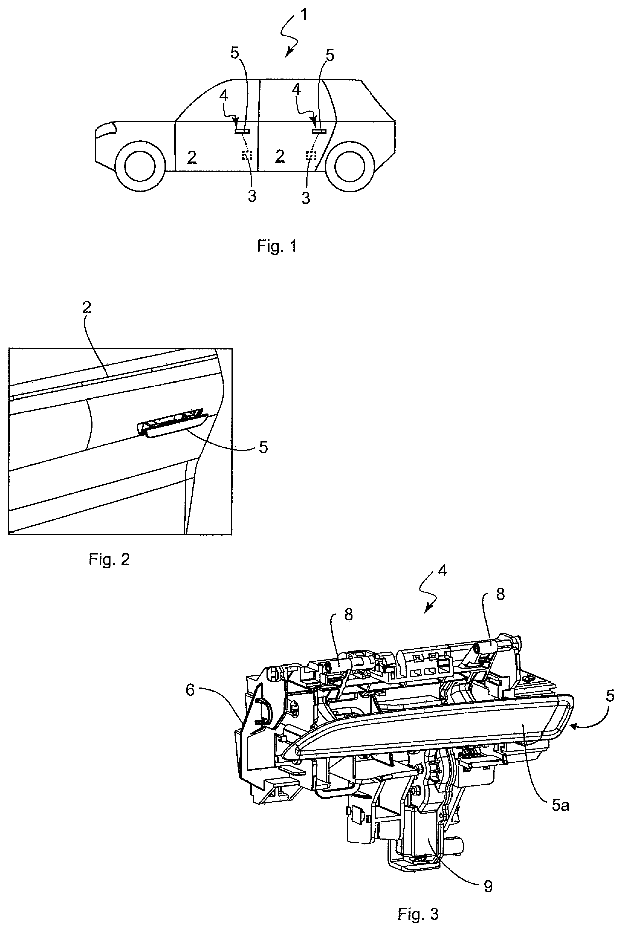
[0035]An exemplary depiction of a motor vehicle 1 in the form of a passenger car is shown in FIG. 1, which has four doors 2 (two of which are shown in FIG. 1) in the example. The doors 2 can be locked via respective motor vehicle locks 3, and can be unlocked using a motor vehicle actuation device 4, merely indicated by way of example in FIG. 1, in that a user actuates a functional element 5 of the motor vehicle actuation device 4 designed as a handle.

[0036]FIG. 2 shows a perspective view of the door 2, in which the functional element 5 protrudes out of the door 2. The functional element 5 is a handle 5a, which is flush with the door 2 in the unactuated stated, attached to pivot arms 7, such that the handle is recessed in the door 2 when not in use.

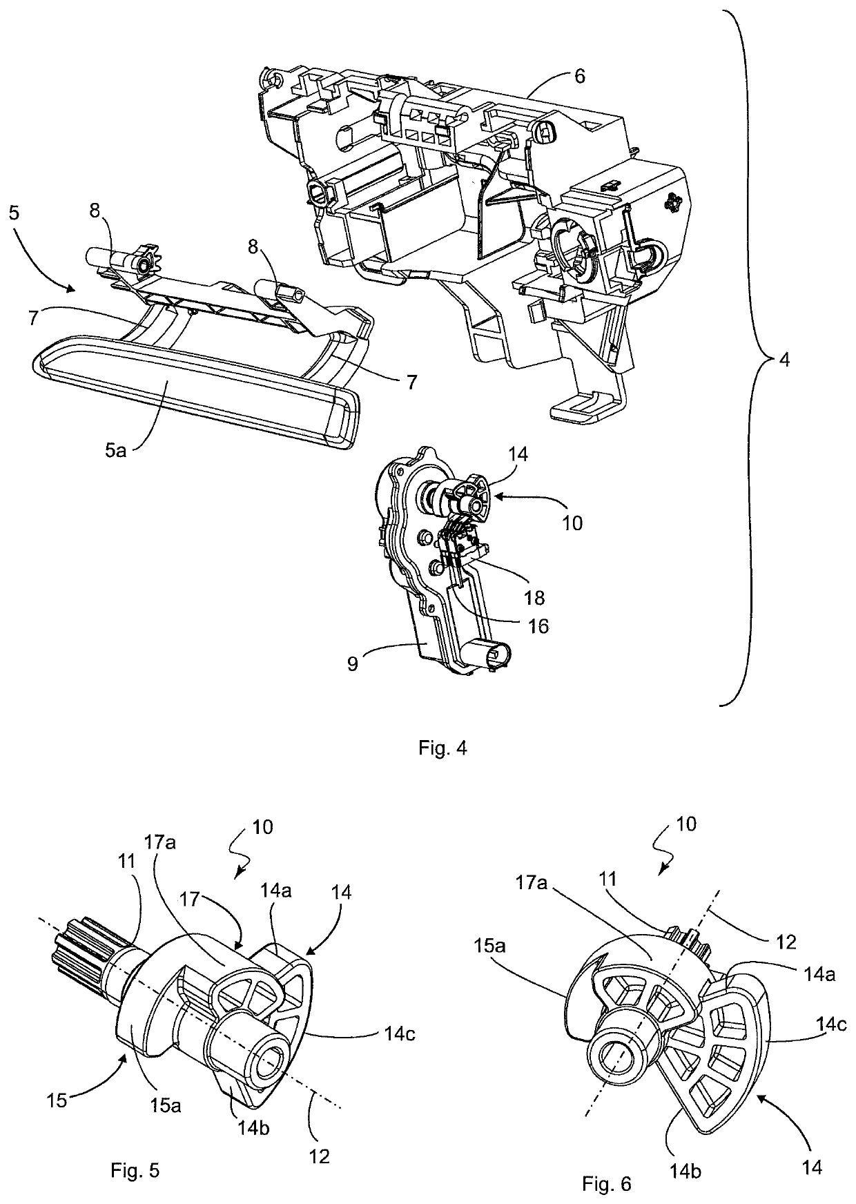
[0037]A perspective view of the motor vehicle actuation device 4 is shown in FIG. 3. The motor vehicle actuation device 4 comprises a carrier housing 6, which is attached on the inside of the door 2, and on which the functional element 5, ...


PUM


Abstract

A motor vehicle actuation device includes a functional element supported on a carrier housing for rotation about a rotational axis and movement between a standby position and an operating position, a drive device disposed on the carrier housing, and a control element in a drive connection with the drive device, which is designed to move the functional element from the standby position into the operating position when the drive device is activated. The control element is moved from a home position into a final actuation position via an initial actuation position when the drive device is activated. The control element forces the functional element from the standby position into the operating position when it moves from the home position into the initial actuation position. The control element retains the functional element in the operating position when it moves from the initial actuation position into the final actuation position.

Description

BACKGROUND[0001]The invention relates to a motor vehicle actuation device that has a carrier housing that can be attached to a motor vehicle, a functional element, which is rotatably supported about a rotational axis on the carrier housing, and can be moved between a standby position and an operating position, a drive device disposed on the carrier housing, and a control element, configured to move the functional element from the standby position to the operating position when the drive device is activated.[0002]A motor vehicle actuation device of the type described above is known, for example, from DE 10 2013 112 706 A1. A control element designed as a lever is connected in a drive connection to a drive device. The drive device moves when the control element is activated, wherein the control element itself is moveably coupled to a functional element in the form of a door handle. As a result of the movement of the control element caused by the drive device, the door handle is extend...

Claims


Application Information

Patent Timeline
Patent Type & Authority Patents(United States)
IPC IPC(8): E05B79/06E05B81/30E05B81/56E05B81/64E05B81/42E05B85/10E05B85/18
CPCE05B85/18E05B79/06E05B81/30E05B81/42E05B81/56E05B81/64E05B85/103E05B85/107E05B79/22
Inventor TORKOWSKI, THORSTENKOCH, ANDREAS
Owner HUF HULSBECK & FURST GMBH & CO KG
Why Eureka
Try Eureka