
Terminal device, infrastructure equipments and methods

a technology of infrastructure equipment and terminals, applied in the direction of location information based services, connection management, instruments, etc., can solve the problems of low power device, long battery life, low complexity devices, etc., and achieve the effect of reducing power consumption, reducing power consumption, and prolonging the discontinuous reception cycl

Active Publication Date: 2021-07-20
SONY CORP +1
View PDF4 Cites 0 Cited by
  • Summary
  • Abstract
  • Description
  • Claims
  • Application Information

AI Technical Summary

Benefits of technology

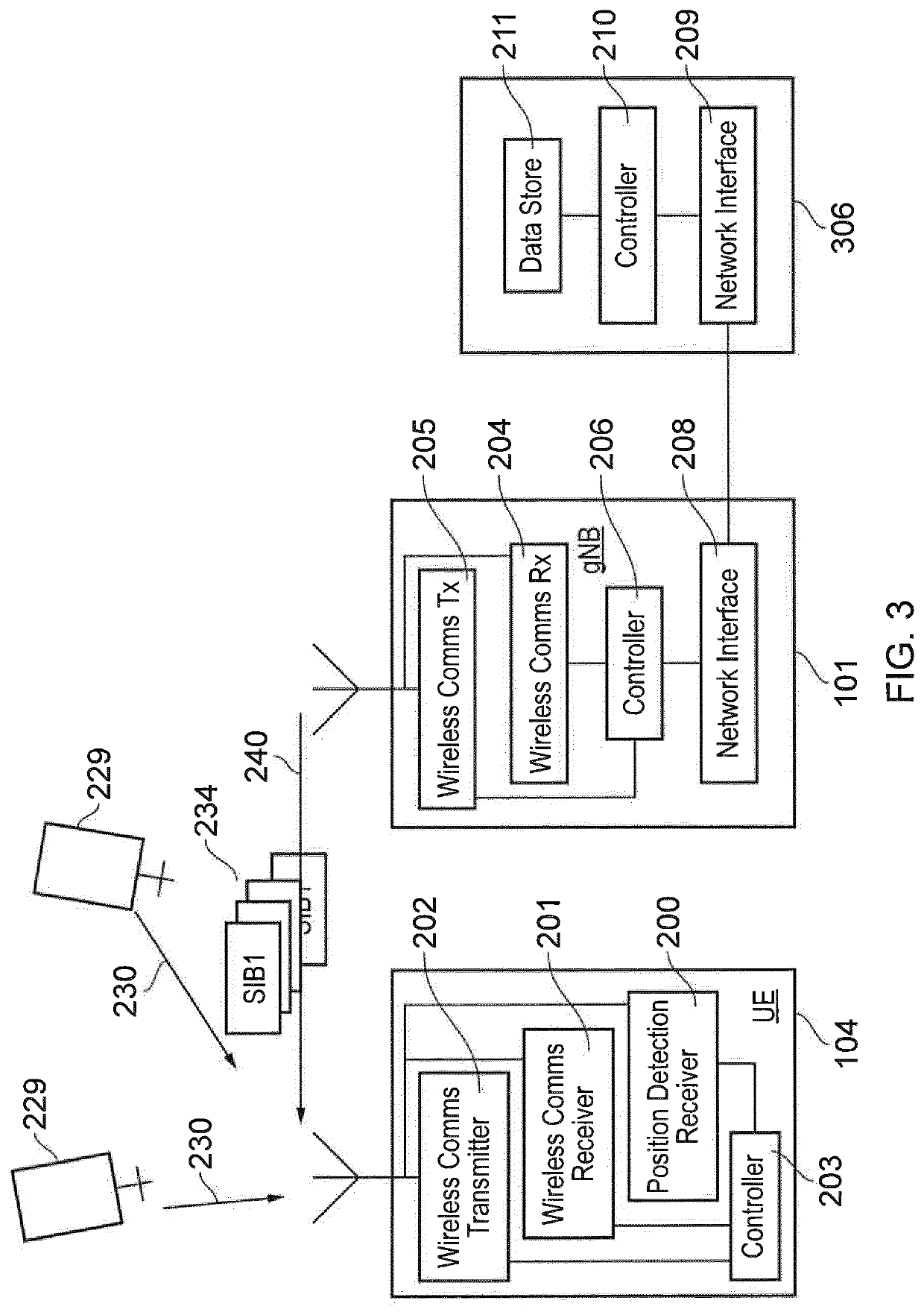
[0009]The present technique is defined according to the claims. According to an example embodiment of the present technique a terminal device comprises wireless communications receiver circuitry configured to receive signals from the infrastructure equipment via a wireless access interface provided by the infrastructure equipment, position detection receiver circuitry configured to receive a radio signal from which measurements can be used to assist in determining a position of the terminal device, and controller circuitry. The controller circuitry is configured to control the wireless communications receiver circuitry to detect one or more system information blocks carrying position assistance information transmitted from the infrastructure equipment, the position assistance information providing information which can be used to assist in determining the position of terminal device, and to control the position detection circuitry to estimate the position of the terminal device by combining the identified position assistance information with the radio signal received by the position detection receiver circuitry. Furthermore the controller circuitry is configured with the wireless communications receiver circuitry to receive from the infrastructure equipment an indication of relative risk that the position assistance information will change, and in response to the indication of the relative risk that the position assistance information will change to adapt the receiving of the one or more system information blocks to receive an updated version of the position assistance information in accordance with the relative risk. The receiving can be adapted for example by changing a period of a discontinuous reception so that if there is a relatively low risk of a change in the position assistance information, UEs can be configured to adopt a longer discontinuous reception (DRX) cycle thereby reducing power consumption. The UEs can adopt a shorter DRX cycle, when there is a greater relative risk of a change in the position assistance information so that the UEs can react more quickly to receive updated position assistance information. As a result the UEs can estimate their position more reliably.
[0011]Embodiment of the present technique can find application with advanced position or location detection techniques which include applications such as machine control, autonomous driving etc. It is expected that in future, position location detection can improve the accuracy of position detection from tens of metres to sub-metre level. For example GPS may be enhanced with GNSS technology improving the accuracy of the position or location detection to less than a metre. As such more critical location applications may be used, such as driverless cars, but these may in turn may cause more severe consequences if there are errors in position accuracy. Embodiments of the present technique can therefore provide improvements in delivering position assistance information to terminal devices to have errors in position detection can be reduced and possible consequences of these errors avoided.

Problems solved by technology

Low complexity devices are also often low power devices, in which it is desirable for such devices to have a low power consumption (and therefore a long battery life).
In particular, the problem of how to efficiently transmit signals to and receive signals from low complexity devices whilst keeping the power consumption of such devices low needs to be addressed.
Configuring terminal device to provide location based services reliably and with low power consumption is therefore a technical problem.
As such more critical location applications may be used, such as driverless cars, but these may in turn may cause more severe consequences if there are errors in position accuracy.

Method used


Image

  • Terminal device, infrastructure equipments and methods
  • Terminal device, infrastructure equipments and methods
  • Terminal device, infrastructure equipments and methods

Examples


Embodiment Construction

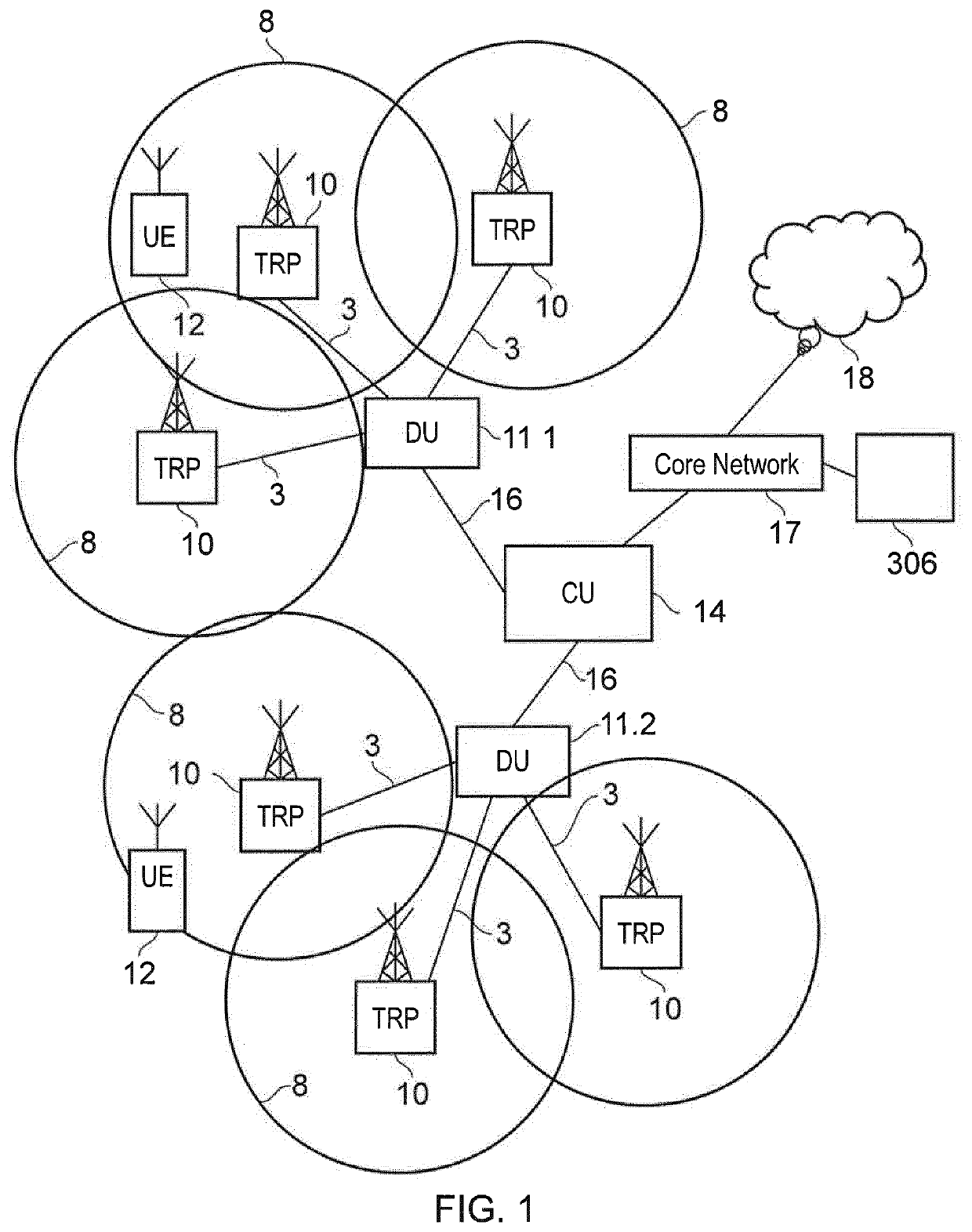
[0021]As mentioned above the embodiments of the present invention can find application with advanced wireless communications systems such as those referred to as LTE, 5G or New Radio Access Technology). New Radio Access Technology has been proposed in [2] to develop a new Radio Access Technology (RAT) for the next generation wireless communication system, i.e. 5G. The new RAT is expected to operate in a large range of frequencies, from hundreds of MHz to 100 GHz and it is expected to cover a broad range of use cases. The use cases that are considered can include:[0022]Enhanced Mobile Broadband (eMBB)[0023]Massive Machine Type Communications (mMTC)[0024]Ultra Reliable & Low Latency Communications (URLLC)

[0025]The aim of 5G is not only mobile connectivity for people, but to provide ubiquitous connectivity for any type of device and any type of application that would benefit from being connected. Many requirements and use-cases are still being discussed, but amongst those are:[0026]Low...


PUM


Abstract

A terminal device configured to receive a radio signal from which measurements can be used to assist in determining a position of the terminal device. The terminal device detects one or more system information blocks carrying position assistance information transmitted from the infrastructure equipment and estimates the position of the terminal device by combining the identified position assistance information with the radio signal received by the position detection receiver circuitry. Furthermore the terminal device receives from the infrastructure equipment an indication of relative risk that the position assistance information will change, and in response to the indication of the relative risk that the position assistance information will change to adapt the receiving of the one or more system information blocks to receive an updated version of the position assistance information in accordance with the relative risk.

Description

CROSS-REFERENCE TO RELATED APPLICATIONS[0001]The present application is based on PCT filing PCT / EP2018 / 082894, filed Nov. 28, 2018, which claims priority to EP 17204751.6, filed Nov. 30, 2017, the entire contents of each are incorporated herein by reference.BACKGROUNDField of the Disclosure[0002]The present technique relates to terminal devices which are configured to generate an estimate of a location of the terminal devices. The present technique also relates to infrastructure equipment and methods, which are configured to provide position assistance information which is used by communications terminals to generate an estimate of their location.Description of the Related Art[0003]The “background” description provided herein is for the purpose of generally presenting the context of the disclosure. Work of the presently named inventors, to the extent it is described in the background section, as well as aspects of the description which may not otherwise qualify as prior art at the t...

Claims


Application Information

Patent Timeline
Patent Type & Authority Patents(United States)
IPC IPC(8): H04W24/00H04W64/00H04W4/20H04W68/00
CPCH04W64/006H04W4/20H04W68/00H04W4/02H04W48/08H04W64/00H04W76/28G01S19/05
Inventor WAKABAYASHI, HIDEJIBERGGREN, ANDERSWEI, YUXINSHARMA, VIVEKTSUDA, SHINICHIRO
Owner SONY CORP
Learn More