Method for controlling the movement of a vitreoretinal viewing system in an ophthalmic surgical microscope, microscope and motion controller for a microscope

a technology of vitreoretinal viewing system and microscope, which is applied in the direction of surgical microscope, mounting, instruments, etc., can solve the problems of front piece contacts, damage or irritation of the cornea of the ey

Active Publication Date: 2021-07-27
LEICA MICROSYSTEMS KK
View PDF7 Cites 0 Cited by
  • Summary
  • Abstract
  • Description
  • Claims
  • Application Information

AI Technical Summary

Benefits of technology

[0011]According to an improved embodiment, a movement of the optics carrier relative to the support is automatically compensated by a counter-movement of the front piece. The counter-movement of the front piece preferably has the same velocity as the movement of the optics carrier. The counter-movement of the front piece is preferably parallel to but directed against the movement of the optics carrier according to a further embodiment. Thus, for the vector v of the velocity of the optics carrier relative to the support and the vector w of the velocity of the vitreoretinal viewing system, the relationship v=−w holds at least during the movement of the optics carrier. Moreover, the movement of the optics carrier and the counter-movement of the front piece may take place simultaneously. If v=−w holds, the optics carrier and the front piece are preferably moved over the same time interval, so that the amount of movement of the front piece relative to the optics carrier compensates exactly the amount of movement of the optics carrier relative to the support.

Problems solved by technology

If the optics carrier is moved, there is a risk that the front piece contacts and thus damages or irritates the cornea of the eye.

Method used


Image

  • Method for controlling the movement of a vitreoretinal viewing system in an ophthalmic surgical microscope, microscope and motion controller for a microscope

Examples


Embodiment Construction

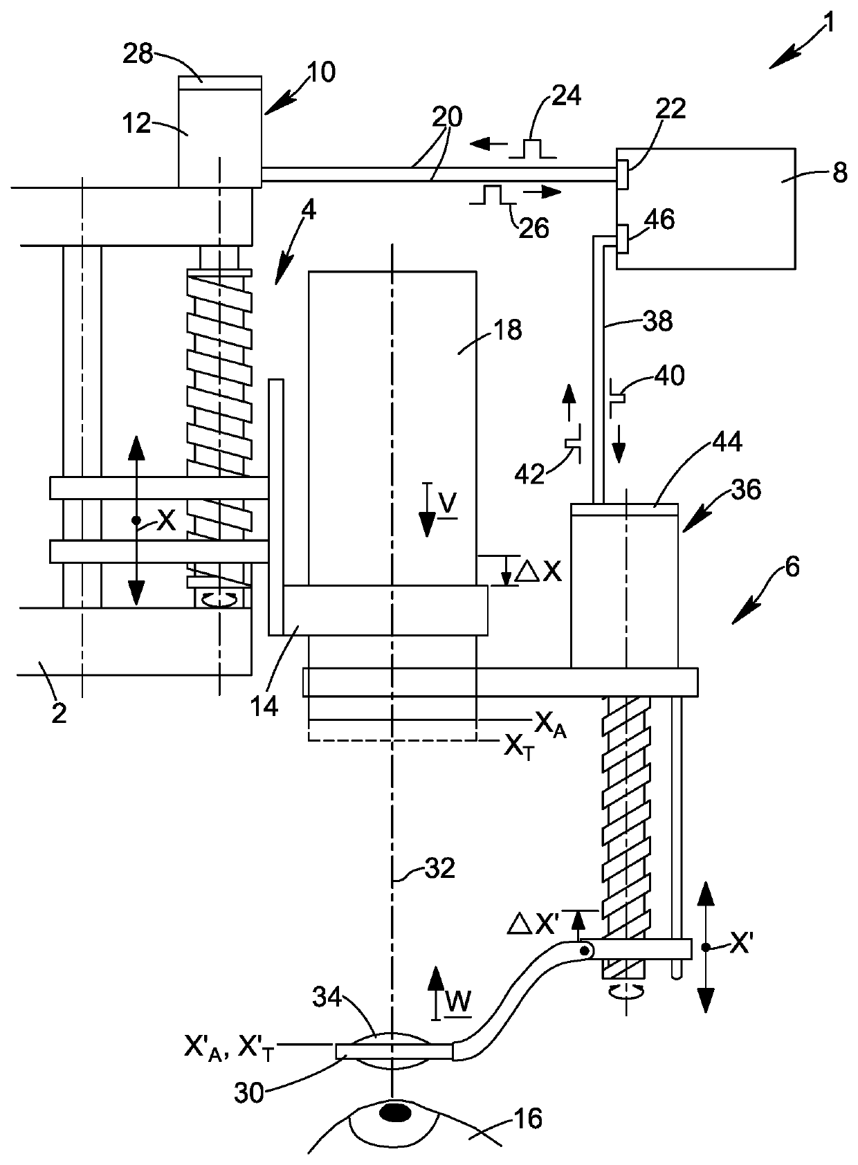
[0016]In FIG. 1, parts of an ophthalmic surgical microscope 1 are shown, namely a support 2 comprising e.g. a stand (not shown) of the microscope for placing the microscope stably onto a floor or a table, a lens positioning system 4, a vitreoretinal viewing system 6 and a motion controller 8.

[0017]The lens positioning system 4 comprises a drive system 10 with an electric motor 12. The electric motor 12 drives a motion-controlled optics carrier 14 relative to the support in a direction x, i.e. towards or away from an observation area 15. During surgery, an eye 16 is located in the observation area 15. The optics carrier 14 is configured to support an optical device such as a microscope lens 18 providing a specific magnification or in the case of a zoom lens, a specific range of magnification. The microscope lens 18 may in particular be a lens which does not have internal focusing. Thus, for adjusting the focus of the lens 18, the optics carrier 14 must be moved in the direction x. Th...


PUM


Abstract

The invention relates to a microscope (1), in particular an ophthalmic surgical microscope having a vitreoretinal viewing system (6), an optics carrier (14) and a support (2). The invention also relates to a method and a motion controller controlling the movement of the vitreoretinal viewing system (6). The optics carrier (14) is attached movably to the support (2). The vitreoretinal viewing system (6) in turn is attached movably to the optics carrier (14). The vitreoretinal viewing system (6) comprises a front piece (30), such as a optics carrier (14). To avoid contact of the front piece (30) with an eye (16) while the optics carrier (14) is moved for focusing a microscope lens (18), the position of the front piece (30) is automatically maintained stationary with respect to the support (2). This is obtained by controlling the vitreoretinal viewing system (6) to perform a counter movement to the movement of the optics carrier (14).

Description

CROSS REFERENCE TO RELATED APPLICATIONS[0001]This application claims priority of European patent application number 17163113.8 filed Mar. 27, 2017, the entire disclosure of which is incorporated by reference herein.FIELD OF THE INVENTION[0002]The invention relates to a method for controlling the movement of a motion-controlled vitreoretinal viewing system in an ophthalmic surgical microscope, a microscope motion controller for an ophthalmic surgical microscope, and a microscope.BACKGROUND OF THE INVENTION[0003]The surgical ophthalmic microscope comprises a motion-controlled vitreoretinal viewing system, a motion-controlled optics carrier and a support. The optics carrier may be adapted to carry at least one microscope lens. For focusing and / or zooming, the optics carrier is moveable with respect to the support, at least in a direction towards and away from the eye. The vitreoretinal viewing system is attached to the optics carrier and is moveable with respect to the optics carrier, ...

Claims


Application Information

Patent Timeline
Patent Type & Authority Patents(United States)
IPC IPC(8): G02B21/02G02B21/00A61B3/13A61B90/20G02B7/00G02B21/24
CPCG02B21/025A61B3/13A61B90/20G02B7/001G02B21/0012G02B21/24G05D3/20
Inventor HONDA, MASATOSHI
Owner LEICA MICROSYSTEMS KK
Why Eureka
Try Eureka