Device to position dumbbells for exercise

a dumbbell and flexible technology, applied in the field of exercise equipment, can solve the problems of inability to use the above-mentioned methods to hold or adjust the dumbbell in a manner in which it can be removed, prior art commercially non-viable, and overwhelming manual methods of positioning dumbbells for exercis

Active Publication Date: 2021-08-31
SHAW JR VINCENT GABRIEL
View PDF13 Cites 11 Cited by
  • Summary
  • Abstract
  • Description
  • Claims
  • Application Information

AI Technical Summary

Benefits of technology

[0019]The present invention comprises a combination of features for inclusion in a device to be used to support dumbbells at the start and conclusion of an exercise “set”. The device is comprised of 1) two surfaces which provide support for the dumbbells to create support in the vertical dimension and which contact the dumbbells on the weighted portion on either side of the dumbbell handle, 2) a surface or surfaces at the rear portion of the support surfaces which prevent rearward travel of the dumbbell beyond the support device (away from the user), 3) a raised “lip or edge at the front portion of the support surface (nearer the user) 4) A vertical surface extending downward from the front “lip” or edge of the support surfaces 5) a series of angles or curves formed into the inside edges of the support surfaces which creates an inward-converging “channel” that guides a user's hand / arm toward the center of the channel while reducing the potential for concentrated contact with any part of the surface, and 6) Generally vertical surfaces extending from the channel boundary to provide a contact surface for the user's arm / hand that will reduce the potential for concentrated contact contained in the prior art.
[0020]The present invention comprises a mechanism to position dumbbells for the start and completion of an exercise set so that the need to lift the dumbbells from the floor, storage rack or other location while in position to perform the exercise is eliminated. This allows dumbbells to be used for strength training in a way similar to how barbells are currently used. It is distinguished from prior art by features including, but not limited to 1) the inclusion of three dimensional positioning (as opposed to simply vertical positioning) 2) the design of the dumbbell holder which allows the dumbbells to be rolled forward or backwards by the user while in position for the exercise for even more precise positioning, 3) the option to attach the dumbbell holders to an existing piece of equipment such as the commonly found “power rack”, 4) the option to attach a second holder which allows the dumbbell to be safely returned to the rack in a case where the user cannot, perhaps due to fatigue or preference, return the dumbbell to the top position on the rack, 5) the option to retract and restore the position of the dumbbell holder during the exercise by means such as a foot control or spring mechanism, 6) a channeling design which guides the user's hand when returning the dumbbell to the holder to reduce risk of injury and the effort required by the user to replace the dumbbell on the device, and 7) a dumbbell holder which allows the dumbbell to be held in position prior to the user assuming the position for the exercise while also allowing the user to move the dumbbell forward and backward on the holder and side-to side by moving the holder through a horizontal arc while in position for the exercise. Two of the dumbbell holders are required to allow the user to position a dumbbell for each hand, and they may either be configured as “stand alone” units which are positioned on either side of a standing, seated or lying user, incorporated as fixed components of a weightlifting apparatus such as a bench-press rack, incorporated as components of a custom integrated stand, or attached to a separate mounting source such as a wall or power rack.

Problems solved by technology

Given the lack of practicality of any of the above art, none of them have been widely adopted and the current common method of positioning a dumbbell for exercise is overwhelmingly manual, with the dumbbell being lifted from the floor or from a storage rack and then moved into positon for the exercise solely by one or more users of the dumbbells.
Additionally, there are numerous devices for positioning a barbell for the start of exercise, however none of these can be used to hold or adjust a dumbbell in a manner in which it can be removed, used for exercise and replaced while the user is in the exercise position.
Another critical advance provided by the present invention is a channeling device using expanded contact areas and a gradual transition from the front of the support to the inner channel which guides the user's hands when returning the dumbbell to the holder: all the prior art subjects the user to an extreme risk of injury and / or discomfort due to the potential for contact between the user's hand, wrist or arm and points of potential concentrated contact on the front or inner channel of the dumbbell holder, and this deficiency alone makes the prior art commercially non-viable due to likely liability risk due to potential for injury to the user.
The primary source of injury risk with such a device is the act of returning the dumbbell to the support device.
In the case of dumbbells however, the user's hands and arms must come in close proximity to the supporting surfaces due to the compact nature of dumbbells.
Furthermore, the user can be expected to often be in a case of extreme tiredness when returning the dumbbells to the rack thereby lessening the degree of precise control of the dumbbell.
Finally, there are numerous types of devices for storing dumbbells in a fitness facility, however none of them are intended or can practically be used to position the dumbbell for the beginning and end of an actual exercise set for most types of dumbbell exercise movements.

Method used


Image

  • Device to position dumbbells for exercise
  • Device to position dumbbells for exercise
  • Device to position dumbbells for exercise

Examples


Embodiment Construction

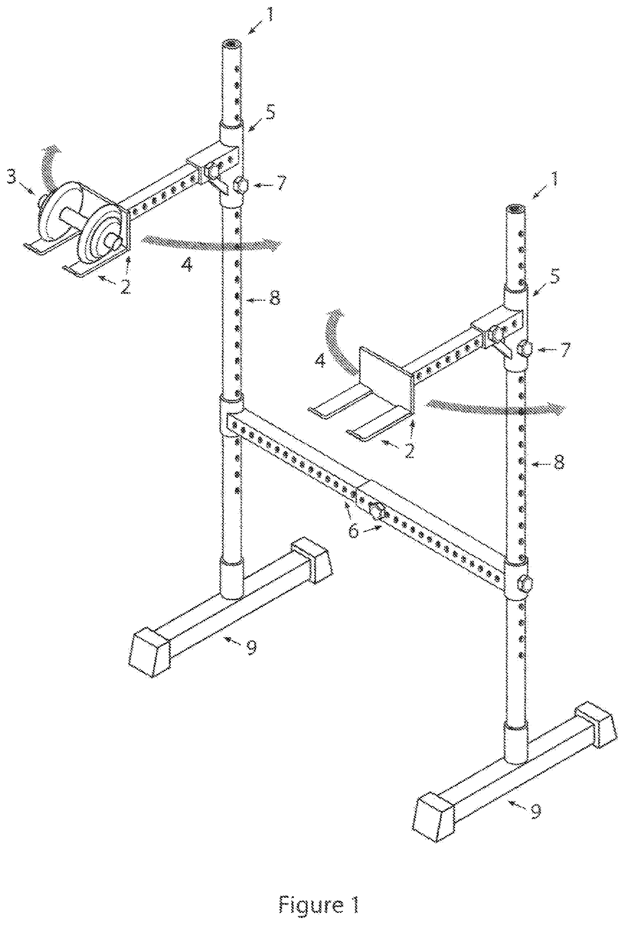
[0065]FIG. 1 shows the invention configured as a free-standing, integrated unit comprised of two supports for two dumbbells holders which would be positioned to deliver dumbbells to each hand of the user who would typically be in either a standing, seated, lying, or incline position to perform the exercise and may have positioned another piece of related equipment nearby such as an incline bench. For example, the user could be seated or lying on an adjacent support when the dumbbells are removed from the rack, or the user could remove them in a standing position, or sit in the type of seat made for seated dumbbell presses to perform the exercise, and then return to a standing position to return the dumbbells to the rack. Any of these would be far easier than lifting the dumbbells from the floor or using a fixed stand which does not allow for extensive tailoring and adjustment of the dumbbell position such as described by the prior art.

[0066]Prior to the exercise, the user would posi...


PUM


Abstract

An apparatus to hold and position dumbbells with adjustment through three dimensions (vertical, horizontal and forward and backward) so as to provide an elevated and precisely positioned starting and ending position for the dumbbells used in a dumbbell exercise. The apparatus may be configured as a stand-alone device, an attachment to another piece of equipment (such as a power rack or bench press) or integrated into another piece of exercise equipment such as a lying / incline / seated press apparatus. It enables adjustment of the dumbbell position by the user while the user is positioned for the exercise, as well as prior to assuming the positon for the exercise, to provide precise positioning as desired by each individual user. It features a channeling device which guides a user's hands, wrists and arms when returning the dumbbell to the holder.Additionally, a support apparatus to hold and position dumbbells for exercise featuring a channel structure which a user's hand, wrist or arm may contact to guide the return of the dumbbell to the support structure, and expanded surface areas on points of the apparatus which a user's body parts may contact which reduce the potential for concentrated contact between a user and the apparatus.

Description

FIELD OF THE INVENTION[0001]The invention relates to the field of exercise equipment. Specifically it provides a device for the flexible positioning of dumbbells for the start and completion of an exercise, similar in concept to racks used to position barbells for exercise.DESCRIPTION OF RELATED ART[0002]Several applications and patents in the prior art show devices which attempt to allow dumbbells to be positioned for the start and finish of an exercise set however nowhere in the prior art is there a dumbbell holding device intended for supporting exercise positioning which includes a self-centering hand / arm guide with expanded contact areas built into the user-facing portion of the center channel of the dumbbell holder to guide a user's return of the dumbbell to the dumbbell holder. Examples of the many differences between the prior art and the present invention include that the prior inventions:[0003]Do not allow for precise movement of the device to position the dumbbell while t...

Claims


Application Information

Patent Timeline
Patent Type & Authority Patents(United States)
IPC IPC(8): A63B21/078A63B21/072
CPCA63B21/078A63B21/0726A63B2225/093A63B23/12A63B71/0036A63B71/0054A63B71/023A63B2071/0063A63B2071/025A63B2208/0204A63B2208/0233A63B2225/09A63B2225/10
Inventor SHAW, JR., VINCENT GABRIEL
Owner SHAW JR VINCENT GABRIEL
Why Eureka
Try Eureka