Particle characterisation instrument

a particle and instrument technology, applied in the field of particle characterisation instruments, can solve the problems of limiting the accuracy of particle characteristics determined from these measurements, difficult to detect scattered light at low angles, and difficult to separate scattered light from incident light, etc., and achieve the effect of increasing capability or accuracy

Active Publication Date: 2021-09-07
MALVERN INSTRUMENTS
View PDF9 Cites 2 Cited by
  • Summary
  • Abstract
  • Description
  • Claims
  • Application Information

AI Technical Summary

Benefits of technology

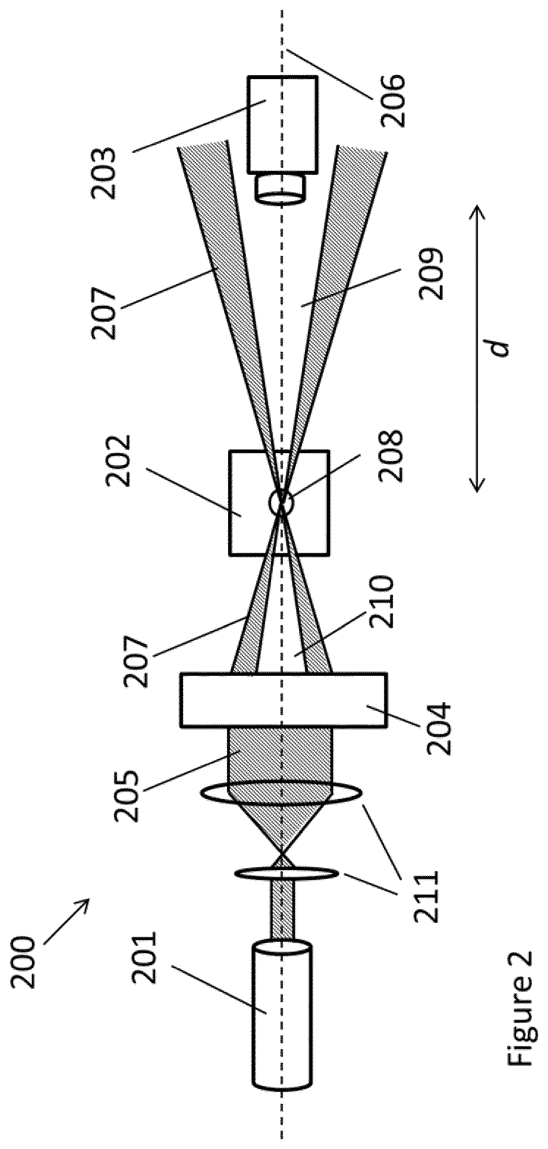
[0013]Modifying the light may comprise diffracting, refracting, obscuring (e.g. with an opaque disc or aperture), reflecting (e.g. with a curved surface, which may also comprise an aperture), or some combination of these effects.
[0044]The body may be configured as a sample holder, for holding a liquid. The body may be configured to hold a sample holder, such as a capillary, or a cuvette with smaller external dimensions than the body. The body may comprise alignment features for accurately aligning a sample holder within the body.
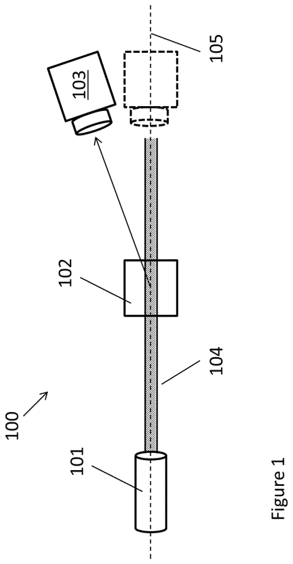
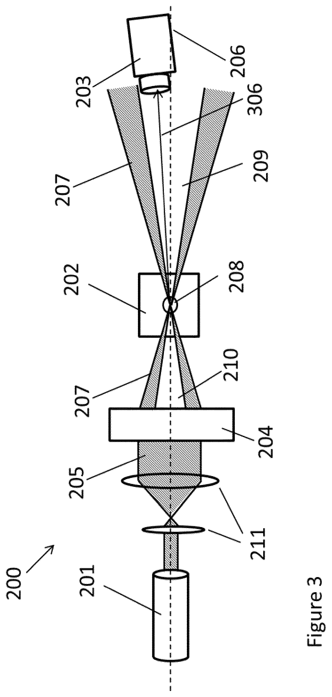
[0055]In any of the example instruments described above, the instrument may further comprise an additional detector configured to detect light scattered from the effective beam by a sample in the sample cell / at the sample position. For example, the additional detector may be positioned or be positionable to detect scattered light along a scattering axis that is at an angle of 85° to 95° from the illumination axis (“side-scattered” light). Alternatively the additional detector may be positioned or be positionable to measure light scattered at any other angles. The additional detector may for example allow measurements of side-scattered light to be taken simultaneously with measurements of zero-angle and / or π-angle scattered light. Simultaneous measurements of light scattered at multiple angles, particularly of light scattered along two orthogonal directions, may provide increased capability or accuracy when extracting particle properties from the measurements. Measurements at multiple angles may also be taken sequentially.

Problems solved by technology

Detecting scattered light at low angles can be difficult.
Separating scattered light from the incident light can be challenging, particularly if the wavelengths and polarisations of the incident and scattered light are the same.
Such assumptions limit the accuracy of the particle characteristics determined from these measurements.
The illuminating light also limits detection of back scattered light.
Not only does the incident light make isolating scatter difficult, but positioning a detector to measure scatter risks obscuring the incident light.

Method used


Image

  • Particle characterisation instrument
  • Particle characterisation instrument
  • Particle characterisation instrument

Examples


example experimental

[0179 results from an instrument using an early prototype obscured lens as the optical element are shown in FIGS. 11 and 12.

[0180]Light scattered from a dispersion of 60 nm latex at angles of 173° (backscatter—non-imaged detection), 17° (forward scatter, non-imaged detection) and nominally zero-angle (imaging optics) was detected. FIG. 11 shows the correlation coefficient for each of these detection angles (line 1201—173°; line 1202—17°; line 1203—zero-angle) as a function of delay time.

[0181]Further data for scattering of 60 nm latex is shown in FIG. 12. This figure shows the correlation function as a function of delay time for scattering angles of 12.8° (line 1301), 3.8° (line 1302), and zero-angle (line 1303).

[0182]In both FIG. 11 and FIG. 12, the prototype zero angle scattering detection has a longer correlation time than the conventional low angle detector approach (of 17° and 3.8° respectively). The exponential form of the correlogram for zero angle detection indicates a singl...


PUM

PropertyMeasurementUnit
angleaaaaaaaaaa
angleaaaaaaaaaa
anglesaaaaaaaaaa

Abstract

A particle characterisation instrument, comprising a light source, a sample cell, an optical element between the light source and sample cell and a detector. The optical element is configured to modify light from the light source to create a modified beam, the modified beam: a) interfering with itself to create an effective beam in the sample cell along an illumination axis and b) diverging in the far field to produce a dark region along the illumination axis that is substantially not illuminated at a distance from the sample cell. The detector is at the distance from the sample cell, and is configured to detect light scattered from the effective beam by a sample in the sample cell, the detector positioned to detect forward or back scattered light along a scattering axis that is at an angle of 0° to 10° from the illumination axis.

Description

REFERENCE TO RELATED APPLICATIONS[0001]This application is a national stage application under 35 USC 371 of International Application No. PCT / EP2017 / 074094, filed Sep. 22, 2017, which claims the priority of European Application No. 16193377.5, filed Oct. 11, 2016, the entire contents of each of which are incorporated herein by reference.FIELD OF THE INVENTION[0002]The invention relates to an instrument for characterising particles, particularly to an instrument for characterising particles by detecting light scattered from a sample containing the particles.BACKGROUND OF THE INVENTION[0003]The scattering of light by a sample is used in various experimental techniques to determine properties of the particles in the sample. For example, electrophoretic light scattering, dynamic light scattering, depolarised dynamic light scattering, and static light scattering can all be used to extract properties of particles such as particle shape, particle size distribution, or molecular weight.[000...

Claims


Application Information

Patent Timeline
Patent Type & Authority Patents(United States)
IPC IPC(8): G01N15/02G01N21/49G01N15/14G01N21/47
CPCG01N15/0211G01N15/1434G01N15/1456G01N21/49G01N2015/0222G01N2015/1454G01N2021/4707G01N2021/4709G01N2201/063G01N2201/0635
Inventor CORBETT, JASONSCULLION, RICHARD
Owner MALVERN INSTRUMENTS
Why Eureka
Try Eureka