
Dental implant device, system and method of use

a dental implant and implant technology, applied in the field of dental implant devices, can solve the problems of difficult to locate and/or discover the underlying anchorage, and the dental implant devices utilized during the intermediate steps of the implant procedure require multiple invasive and costly procedures

Active Publication Date: 2021-09-14
ABRACADABRA IMPLANT LTD
View PDF33 Cites 0 Cited by
  • Summary
  • Abstract
  • Description
  • Claims
  • Application Information

AI Technical Summary

Benefits of technology

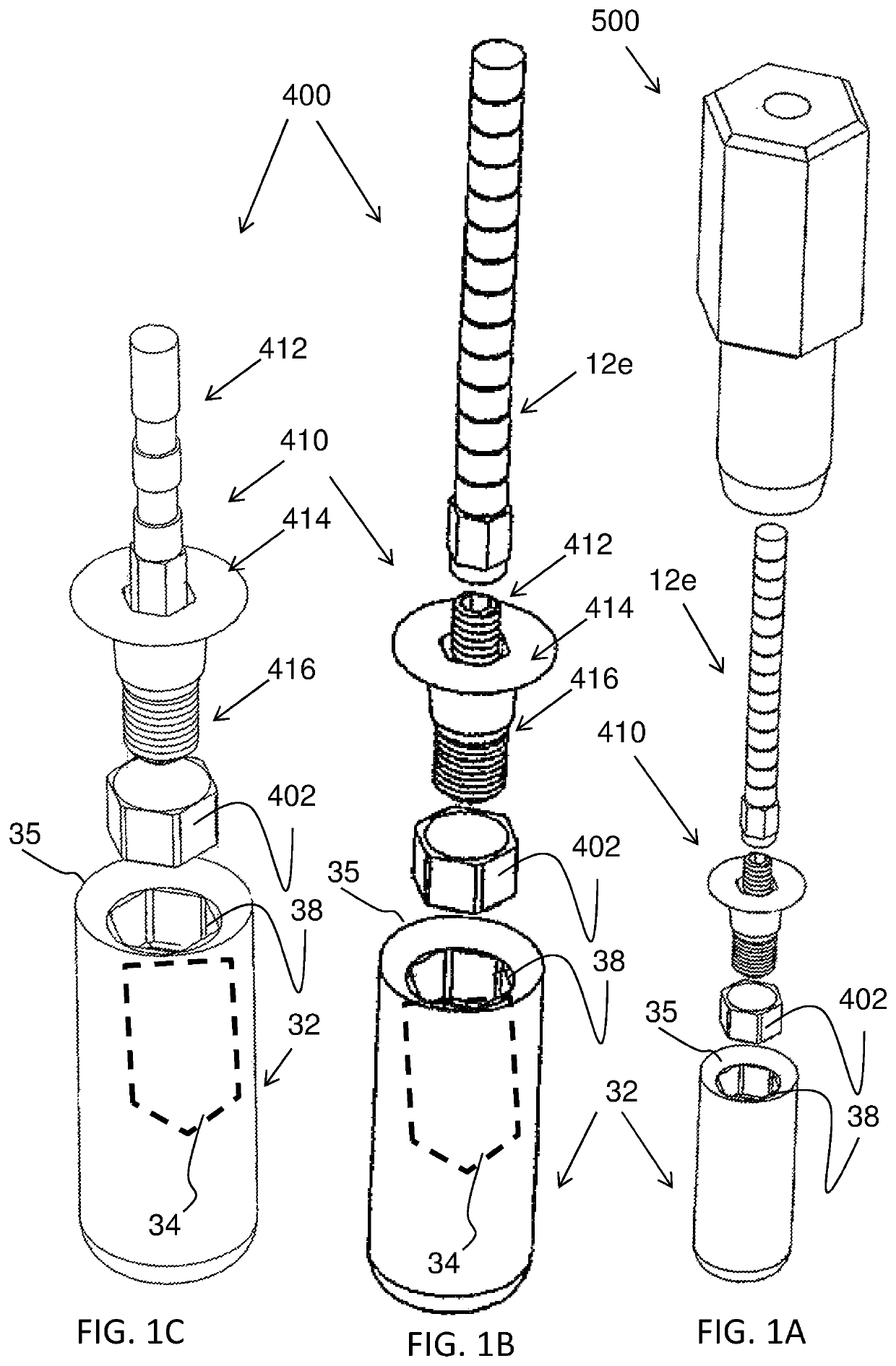
[0011]The dental implant device, system and method of use according to embodiments of the present invention provide for a non-invasive and a-traumatic method that remotely treats the peri-implant tissue to promote faster healing, while significantly reducing the number of procedures and care-giver iterations required between anchor implantation and loading. The dental implant device of the present invention further facilitates the implantation process by providing for readily identifying the location, orientation and axis of the implanted dental implant anchor in a non-invasive manner, for example by visual inspection. The dental implant device according to embodiments of the present invention further provides for minimizing peri-implant host tissue loss during the process of discovering and uncovering of the implant anchor, which takes place prior to implant loading.
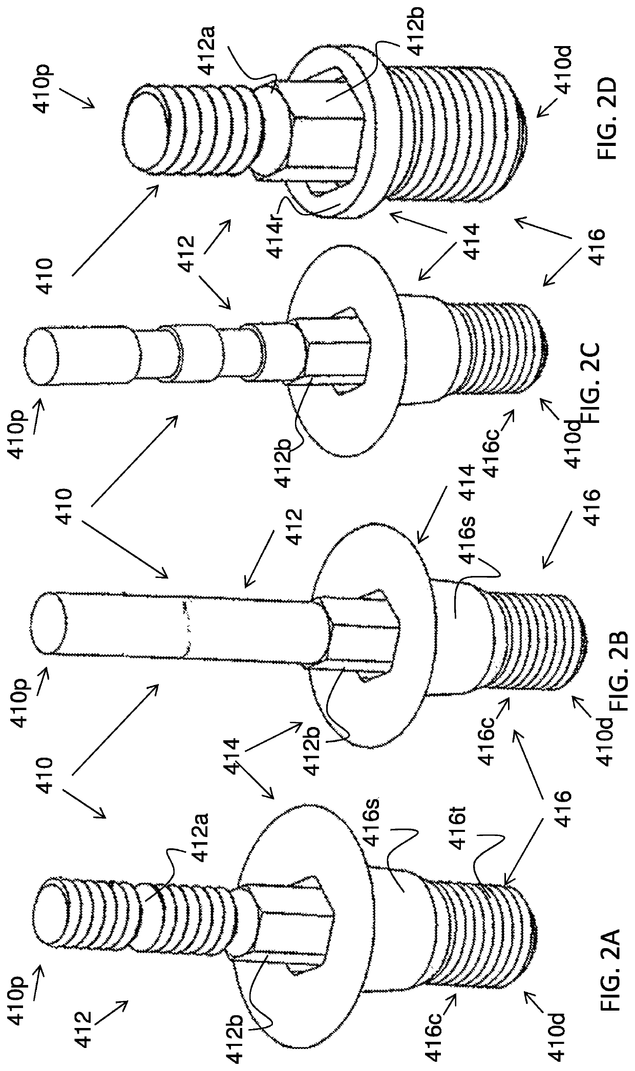
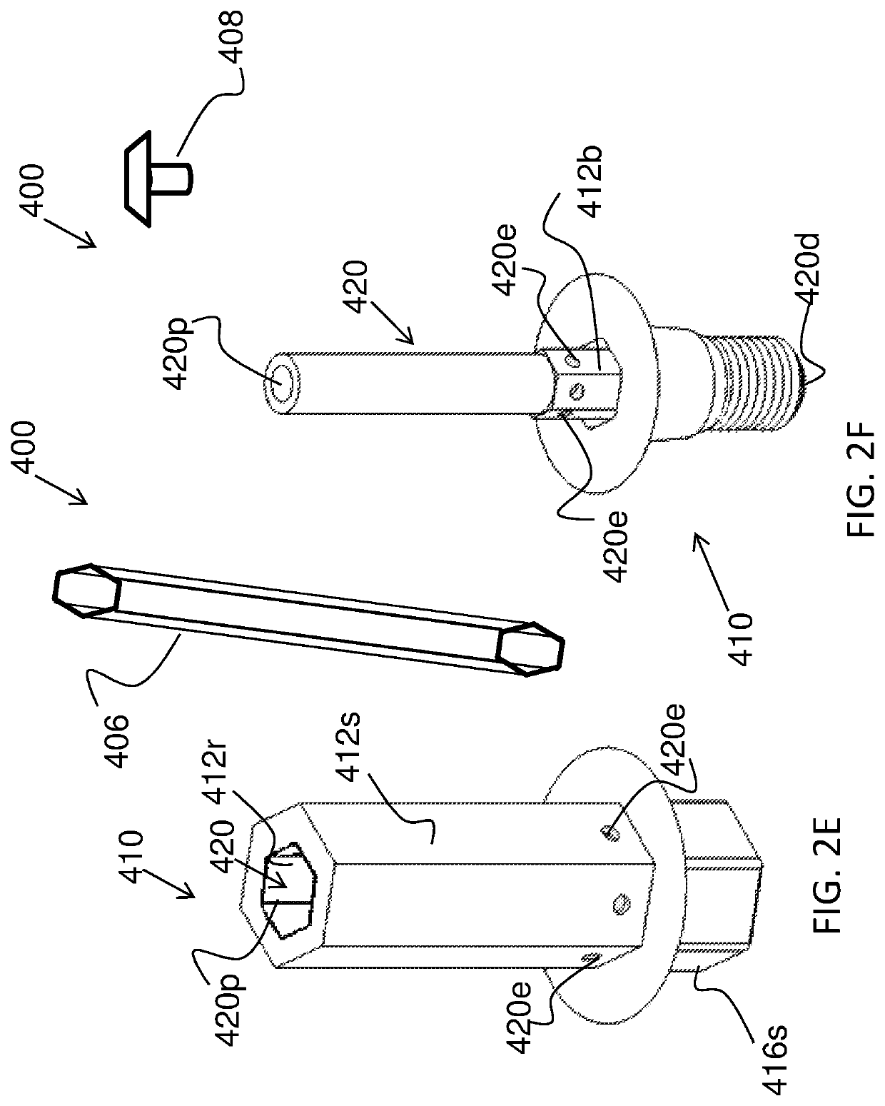
[0048]An optional embodiment of the present invention provides a method for reducing the number of intermediate procedures required between a dental anchor placement to the abutment and restoration loading during a dental implant restoration procedure, the method comprising: a) Associating the implant device having a medial portion including a peri-implant collar portion, that is coupled with a dental implant anchor during implant anchor placement; b) Monitoring the healing of the gingival tissue while providing a-traumatic and minimally invasive treatment to the peri-implant tissue as needed via proximal portion channel, the treatment selected from, tissue irrigation, introduction of a medicament to the peri-implant tissue, shaping and protecting the peri-implant tissue with medial portion having a peri-implant collar; c) Facilitating digital or analog impression coping of the implantation site wherein the proximal portion of the implant device facilitates the identification of the orientation and geometry of the connection platform aperture of the implant anchor with at least one feature selected from: a marker disposed on along the proximal portion, the external surface of proximal portion, inner luminal surface of channel, proximal end aperture, the feature serves as a reference correlating and corresponding to the orientation and geometry of the anti-rotational connection platform aperture of implant anchor; d) a-traumatically anesthetizing the peri-implant tissue by introducing anesthetics from the proximal portion channel through at least one exit pore; e) uncovering the implant anchor and minimizing the peri-implant tissue loss over the implant anchor's occlusal portion by guiding a tissue punch device along the proximal portion of the implant device of the present invention; and f) disassociating the implant device from the anchor and proceeding to load the implant with an abutment and restoration.

Problems solved by technology

State of the art dental implant devices utilized during the intermediate steps of the implant procedure require multiple invasive and costly procedures.
Following the implantation of a dental implant anchor, the anchor is not easily discoverable following the healing period.
This is due to that fact that during the healing process, the morphology of the gingival tissue covering the anchor is restored, making it difficult to locate and / or discover the underlying anchor.
During the anchor uncovering process much of the host tissue is needlessly lost.
Such tissue loss can lead to various medical drawbacks for example, vertical bone loss, prolonged re-healing period, formation of closed and inaccessible voids, pockets, cysts, formation of fibrotic tissue, improper sealing possibly leading to contamination, overlapping of the anchor's margins with proliferated neo-tissue leading to inadequate abutment coupling and loosening.

Method used


Image

  • Dental implant device, system and method of use
  • Dental implant device, system and method of use
  • Dental implant device, system and method of use

Examples


Embodiment Construction

[0067]The present invention relates to a dental implant device and a method for using the same and in particular, to such a device and method in which the implant device provides a projection of the implant anchor's connection platform, location, orientation and axis while facilitating a-traumatic, non-invasive treatment of the peri-implant tissues from a remote location above the host peri-implant tissue.

[0068]The dental implant device, system and method of use according to embodiments of the present invention provide for a non-invasive and a-traumatic method that remotely treats the peri-implant tissue to promote faster healing, while significantly reducing the number of procedures and care-giver iterations required between anchor implantation and loading. The dental implant device of the present invention further facilitates the implantation process by providing for readily of identifying the location, orientation and axis of the implanted dental implant anchor in a non-invasive ...


PUM


Abstract

A dental device and a method of use for associating with an implanted dental implant anchor immediately following implantation. The device provides for projecting the implant's location, orientation and axis such that the device is readily visible to the naked eye by way of visual inspection so as to reveal the location of the implanted dental implant anchor following a healing period. The device having a distal portion, for coupling to the dental implant, a medial portion, for covering the proximal end of the dental implant, and a proximal portion, defining a vertically adjustable shaft provided for projecting the location, orientation and axis of implant anchor.

Description

[0001]This Application is a national phase of, and claims priority from, PCT Application No. PCT / IL2014 / 050511, filed on Jun. 6, 2014, which claims priority from U.S. Provisional Application No. 61 / 831,633, filed Jun. 6, 2013, which is hereby incorporated by reference as if fully set forth herein.FIELD OF THE INVENTION[0002]The present invention relates to a dental implant device and a method for using the same and in particular, to such a device and method in which the implant device projects the implant anchor's location, orientation and axis while facilitating the treatment of the peri-implant tissues.BACKGROUND OF THE INVENTION[0003]Dental implants are well known in the art and typically include a dental implant anchor securely inserted into the patient's jawbone, an abutment member attached to the dental anchor, and a prosthodontic restoration coupled thereon.[0004]The method of implantation generally occurs over various stages where that generally initiates with the implant an...

Claims


Application Information

Patent Timeline
Patent Type & Authority Patents(United States)
IPC IPC(8): A61C9/00A61C8/00A61B90/00
CPCA61C8/008A61C8/0001A61C8/006A61C8/0074A61C8/0089A61C9/004A61B2090/3904A61B2090/3937
Inventor HONIG, IULIAN
Owner ABRACADABRA IMPLANT LTD
Learn More