Adaptive antenna configuration

a technology of antenna configuration and adapter, applied in the field of mobile telecommunications, can solve the problems of ghz sampling rate, less than optimal beam configuration, need for beam management, etc., and achieve the effect of reducing the frequency, reducing the cost of operation, and saving battery power

Active Publication Date: 2021-09-28
SONY CORP
View PDF15 Cites 0 Cited by
  • Summary
  • Abstract
  • Description
  • Claims
  • Application Information

AI Technical Summary

Benefits of technology

[0021]Thus, objects, features, aspects and advantages of the present invention include, but are not limited to, selecting an antenna configuration from amongst a plurality of available antenna configurations based on the quality of a received wireless signal. Such an open loop selection process eliminates the need to include other network nodes in the antenna configuration selection process.
[0022]Additional objects, features, aspects and advantages of the present invention provide for selecting the antenna configuration so as to optimize the rate (e.g., capacity), robustness and power efficiency (e.g., current consumption) of the communication for different network scenarios. In this regard, the present invention balances the need for acceptable signal quality with the need to conserve battery power.

Problems solved by technology

However, use of multiple antenna elements results in the need for beam management and beam synchronization.
However, in other specific scenarios beam configuration is less than optimal.
The wide bandwidth available in the mm-wave frequency spectrum presents unique challenges, in that, the analog-to-digital converter (ADC) or digital-to-analog converter (DAC) sampling rate needs to be twice the bandwidth; resulting in GHz sampling rates.
Such high frequency sampling rates leads to high current consumption in the UE.
However, in some cases, use of a single antenna element gives rise to problems with multipath effects.
The late arrival of scattered portions of the signal causes problems such as fading, cut-out, and intermittent reception.
In digital wireless communications systems such scattering can cause a reduction in data speed and an increase in the number of errors.

Method used


Image

  • Adaptive antenna configuration
  • Adaptive antenna configuration
  • Adaptive antenna configuration

Examples


Embodiment Construction

[0037]Embodiments of the present invention now may be described more fully hereinafter with reference to the accompanying drawings, in which some, but not all, embodiments of the invention are shown. Indeed, the invention may be embodied in many different forms and should not be construed as limited to the embodiments set forth herein; rather, these embodiments are provided so that this disclosure may satisfy applicable legal requirements. Like numbers refer to like elements throughout.

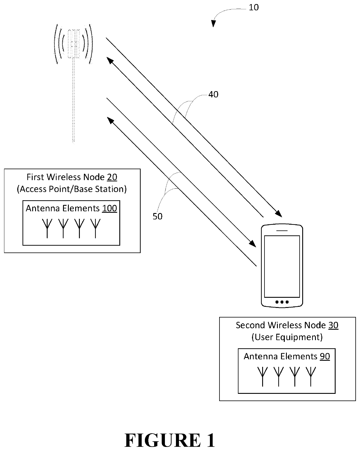
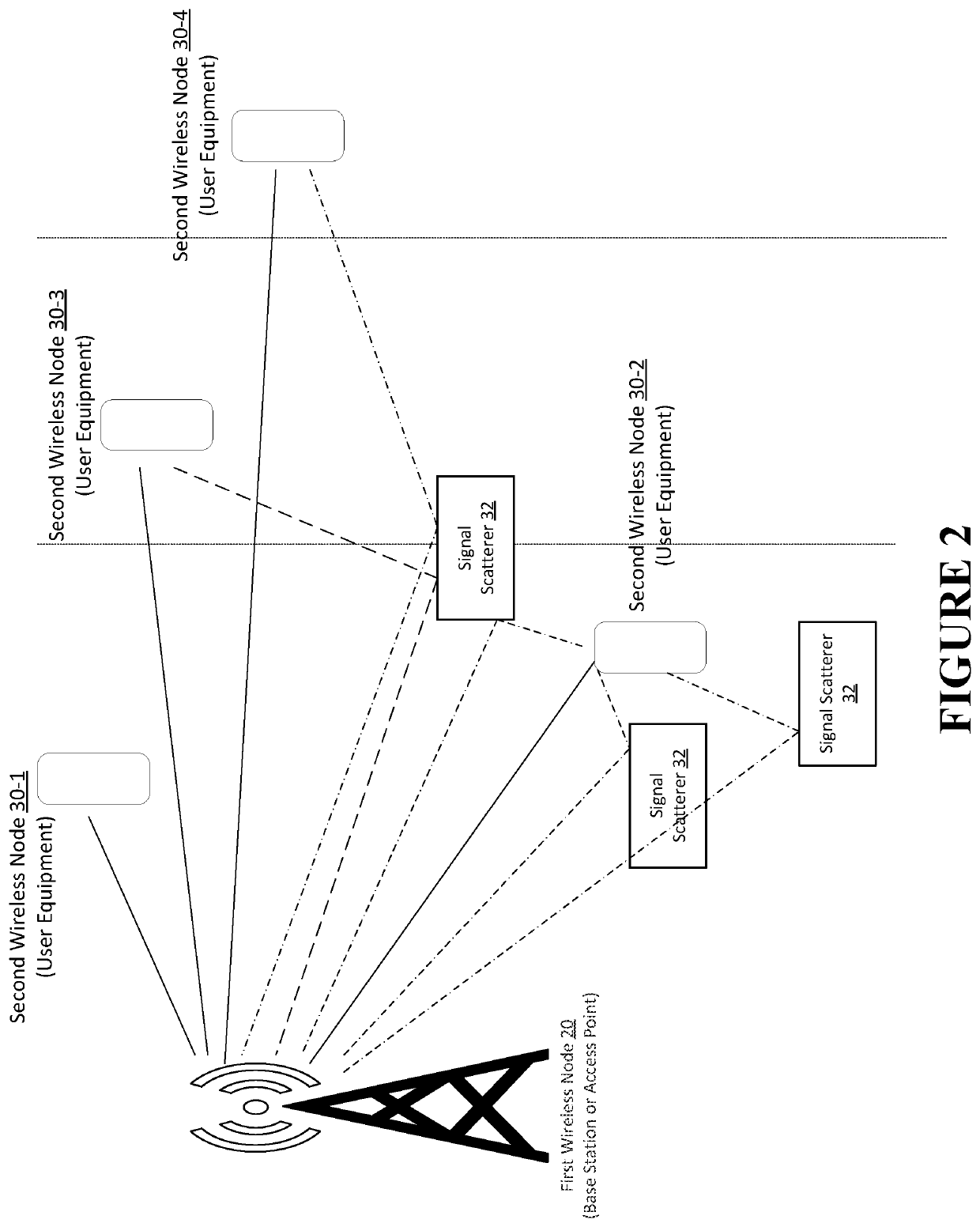
[0038]A wireless node as used herein, may refer to user equipment (“UE”), such as a mobile terminal / device, an access point (“AP”) or a base stations (“BS”), otherwise referred to as an eNodeB (eNB), gNodeB (gNB) or the like. For the purpose of sending or receiving data, the UE may connect to a wireless local area network (“WLAN”) or a mobile communication network (including evolution of 3GPP) LTE releases and 5th Generation (“5G”) New Radio (NR) releases) comprising a plurality of APs and / or BSs.

[003...


PUM


Abstract

Adaptive selection of antenna configurations by wireless nodes that comprise a plurality of antenna elements adapted for a plurality of different antenna configurations. The selection of the antenna configuration is made based on the quality of signal(s) received by the wireless node. The wireless nodes are operable for communication in the mm-wave frequency band and, in specific embodiments, the different antenna configurations include two or more of a wide-coverage area antenna configuration, a Multiple-Input Multiple-Output (MIMO) configuration and a Beamforming (BF) configuration.

Description

CROSS REFERENCE TO RELATED APPLICATION[0001]This application is a 35 U.S.C. § 371 national stage application of PCT International Application No. PCT / US2017 / 037444, filed on Jun. 14, 2017, the content of which is incorporated herein by reference in its entirety. The above-referenced PCT International Application was published in the English language as International Publication No. WO 2018 / 231217 A1 on Dec. 20, 2018.FIELD OF THE INVENTION[0002]In general, embodiments of the invention relate to mobile telecommunications and, more particularly, methods, apparatus, computer program products and the like for adaptive antenna configuration of wireless nodes for operation in the mm-wave frequency band.BACKGROUND[0003]Future radio communications, such as NR (New Radio) or 5G (5th Generation) wireless communication, will rely on the millimeter (mm)-wave frequency spectrum for communication. Operation of radio communications in the mm-wave frequency band is attractive as the available bandwi...

Claims


Application Information

Patent Timeline
Patent Type & Authority Patents(United States)
IPC IPC(8): H04W16/28H04B7/0413H04B7/06H04W24/02
CPCH04W16/28H04B7/0413H04B7/0617H04W24/02H04B7/0689
Inventor BENGTSSON, ERIKBOLIN, THOMASZANDER, OLOFYING, ZHINONGKARLSSON, PETER C.
Owner SONY CORP
Why Eureka
Try Eureka