Supercharge Your Innovation With Domain-Expert AI Agents!

Liquid crystal display device

a display device and liquid crystal technology, applied in non-linear optics, instruments, optics, etc., can solve the problems insufficient improvement of display quality, and achieve the effect of reducing display quality from falling

Active Publication Date: 2021-10-19
SHARP KK
View PDF12 Cites 0 Cited by
  • Summary
  • Abstract
  • Description
  • Claims
  • Application Information

AI Technical Summary

Benefits of technology

[0008]In view of the foregoing problems, it is an object of the disclosure to restrain display quality from falling due to alignment singularities in liquid crystal display devices including pixels each having a reflection region.
[0018]The embodiments of the disclosure restrain display quality from falling due to alignment singularities in liquid crystal display devices including pixels each having a reflection region.

Problems solved by technology

The inventors of the disclosure have thoroughly investigated the provision of openings in an electrode disposed on the color filter substrate (“opposite electrode”) as a way of reducing the generation of these bubbles and found that display quality does not improve sufficiently if openings are provided simply in the opposite electrode.
Specifically, as will be described later in more detail, when there are provided openings in the opposite electrode in a memory liquid crystal display device that operates by area coverage modulation, orientation becomes unstable in some regions (alignment singularities), which in turn causes, for example, image sticking, hence lower display quality.

Method used


Image

  • Liquid crystal display device
  • Liquid crystal display device
  • Liquid crystal display device

Examples


embodiment 1

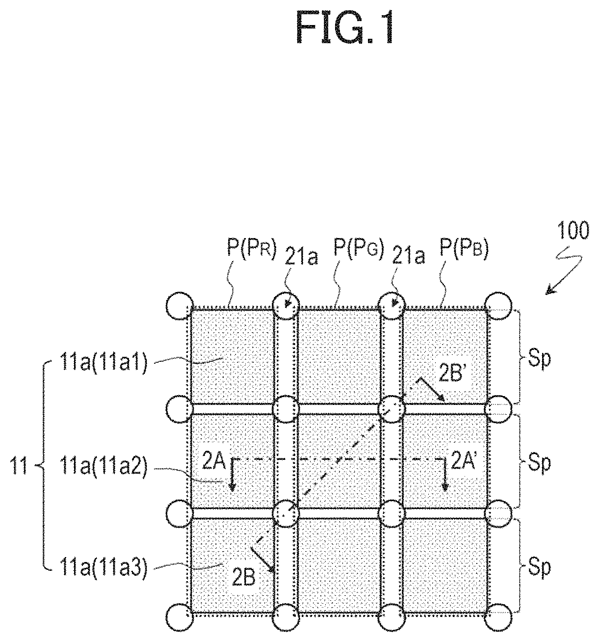
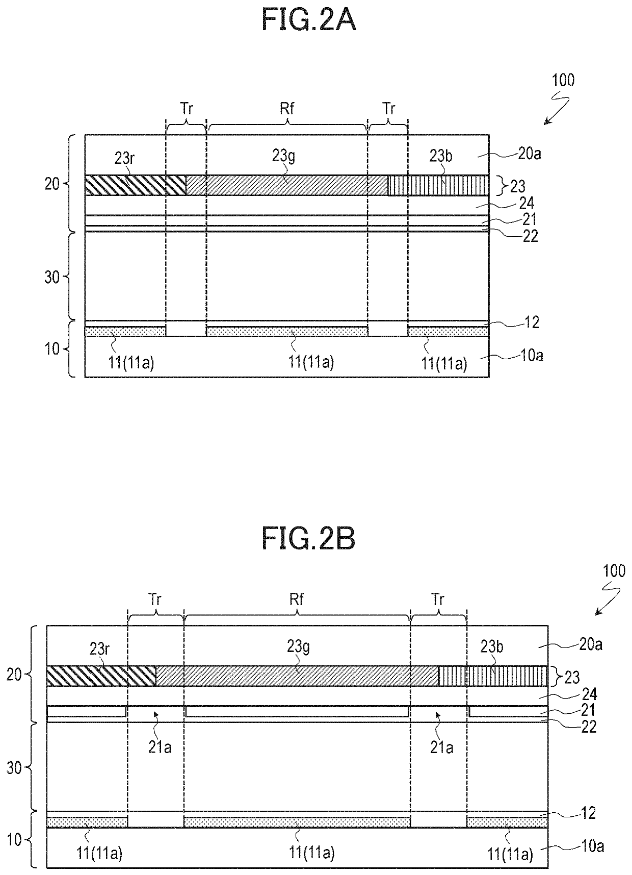
[0037]A description will be given of a liquid crystal display device 100 in accordance with the present embodiment with reference to FIGS. 1, 2A, and 2B. The liquid crystal display device 100 in accordance with the present embodiment is a transflective liquid crystal display device (transmission / reflection combination type of liquid crystal display device). FIG. 1 is a schematic plan view of the liquid crystal display device 100, illustrating regions for three pixels P in the liquid crystal display device 100. FIGS. 2A and 2B are schematic cross-sectional views of the liquid crystal display device 100, illustrating a cross-sectional structure thereof taken along lines 2A-2A′ and 2B-2B′ in FIG. 1 respectively.

[0038]The liquid crystal display device 100 includes the pixels P as shown in FIG. 1. The pixels P are arranged in a matrix of rows and columns (FIG. 1 shows the three pixels P arranged in a 1 row and 3 columns). Each pixel P consists typically of a red pixel PR for a display in...

embodiment 2

[0086]A description will be given of a liquid crystal display device 200 in accordance with the present embodiment with reference to FIGS. 8 and 9. The liquid crystal display device 200 in accordance with the present embodiment is a transflective liquid crystal display device (transmission / reflection combination type of liquid crystal display device). FIG. 8 is a schematic plan view of the liquid crystal display device 200, illustrating regions for three pixels P in the liquid crystal display device 200. FIG. 9 is a schematic cross-sectional view of the liquid crystal display device 200, illustrating a cross-sectional structure thereof taken along line 9A-9A′ in FIG. 1. The following description will focus on differences between the liquid crystal display device 200 and the liquid crystal display device 100 in accordance with Embodiment 1.

[0087]The opposite electrode 21 in the present embodiment has openings 21a in areas corresponding to some of the corners (the upper right corners ...


PUM

PropertyMeasurementUnit
distanceaaaaaaaaaa
distanceaaaaaaaaaa
heightaaaaaaaaaa

Abstract

Each pixel has a reflection region to produce a display in reflection mode. The first substrate includes: a pixel electrode for each pixel; and a first vertical alignment film. The second substrate includes: an opposite electrode opposite the pixel electrodes; and a second vertical alignment film. Of the first and second vertical alignment films, only the second vertical alignment film exerts an alignment-regulating force that determines a pretilt angle. Each pixel electrode includes a plurality of subpixel electrodes. The opposite electrode has an opening in an area corresponding to one of four corners of at least one of the plurality of subpixel electrodes. Liquid crystal molecules in a thickness-wise middle portion of the liquid crystal layer on the subpixel electrode are oriented toward the opening.

Description

CROSS-REFERENCE TO RELATED APPLICATION[0001]The present application claims priority from Japanese Application JP 2020-022156, filed Feb. 13, 2020, the content to which is hereby incorporated by reference into this application.BACKGROUND1. Technical Field[0002]The disclosure relates generally to liquid crystal display devices and in particular to liquid crystal display devices including pixels each having a reflection region.2. Description of the Related Art[0003]Liquid crystal display devices can be roughly classified into two types: transmissive and reflective. The transmissive liquid crystal display device relies on the light emitted by a backlight for a display in transmission mode. The reflective liquid crystal display device relies on ambient light for a display in reflection mode. Another type of liquid crystal display device is being proposed that includes pixels each having both a reflection region for a display in reflection mode and a transmission region for a display in t...

Claims


Application Information

Patent Timeline
Patent Type & Authority Patents(United States)
IPC IPC(8): G02F1/1337G02F1/1343G02F1/137G02F1/1335
CPCG02F1/133773G02F1/13439G02F1/13712G02F1/133555G02F1/133742G02F1/133765G02F1/134309G02F1/133707G02F1/133784G02F2203/02G02F2203/01
Inventor INA, KEIICHISATOH, TAKASHISASAKI, TAKAHIRO
Owner SHARP KK
Features
  • R&D
  • Intellectual Property
  • Life Sciences
  • Materials
  • Tech Scout
  • Unparalleled Data Quality
  • Higher Quality Content
  • 60% Fewer Hallucinations
Learn More