
Bale wrapping assembly for a round baler

a baler and assembly technology, applied in baling, agriculture tools and machines, agriculture, etc., can solve the problems of difficult to efficiently and reliably attach the final length of the twine to the completed, the risk of undetected twine insertion in the groove is often no longer easily visible, and the detectability of the twine is maximized. , the impact on the consistency of the bale is minimized

Active Publication Date: 2021-11-02
BLUE LEAF I P INC
View PDF16 Cites 0 Cited by
  • Summary
  • Abstract
  • Description
  • Claims
  • Application Information

AI Technical Summary

Benefits of technology

[0013]In this way the twine is reliably secured to the outer circumferential surface of the bale as it is intermittently introduced into the completed bale thereby increasing frictional forces acting on the twine. This is realized in a way that reduces impact on the consistency of the bale and has a reduced risk of undetected lengths of twine as no longer a continuous groove is created that impacts the consistency of the bale and the twine is only intermittently introduced in to the bale whereby it remains visibly detectable more easily.
[0062]In this way detectability of the twine is maximized while the impact on the consistency of the bale is minimized.

Problems solved by technology

One particular problem with these known bale wrapping assemblies is the difficulty to efficiently and reliably attach the final lengths of the twines to the completed bale, such that they are not causing problems during subsequent handling operations when a certain length of twine is no longer engaged with the outer circumferential surface of the completed bale.
A problem with such systems is that they affect the consistency of the bale as the means that create a groove do this into the entire circumference of the bale, some systems even create such groove not only in the outer circumferential surface of the completed bale, but in all crop layers during the bale forming process still further aggravating this problem.
Additionally when the final lengths of twine are successfully introduced into this groove during the wrapping operation, this facilitates the subsequent handling operations, but provides for a new problem during subsequent feeding operations in which the bales are provided to animals as fodder.
The lengths of twine inserted in these grooves are often no longer easily visible which increases the risk that lengths of twine inserted in these grooves will remain undetected during removal of the twine around the bale in preparation of a feeding operation.
Such undetected twines present amongst the crop serving as fodder can pose a health risk for the animals.

Method used


Image

  • Bale wrapping assembly for a round baler
  • Bale wrapping assembly for a round baler
  • Bale wrapping assembly for a round baler

Examples


Embodiment Construction

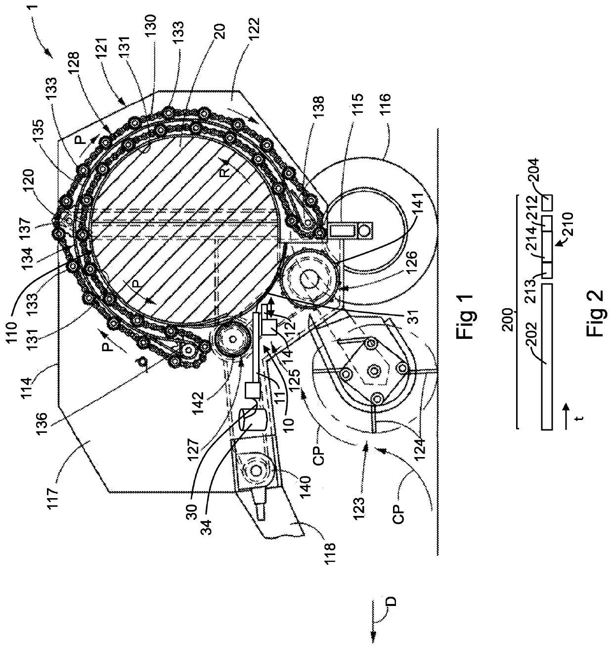
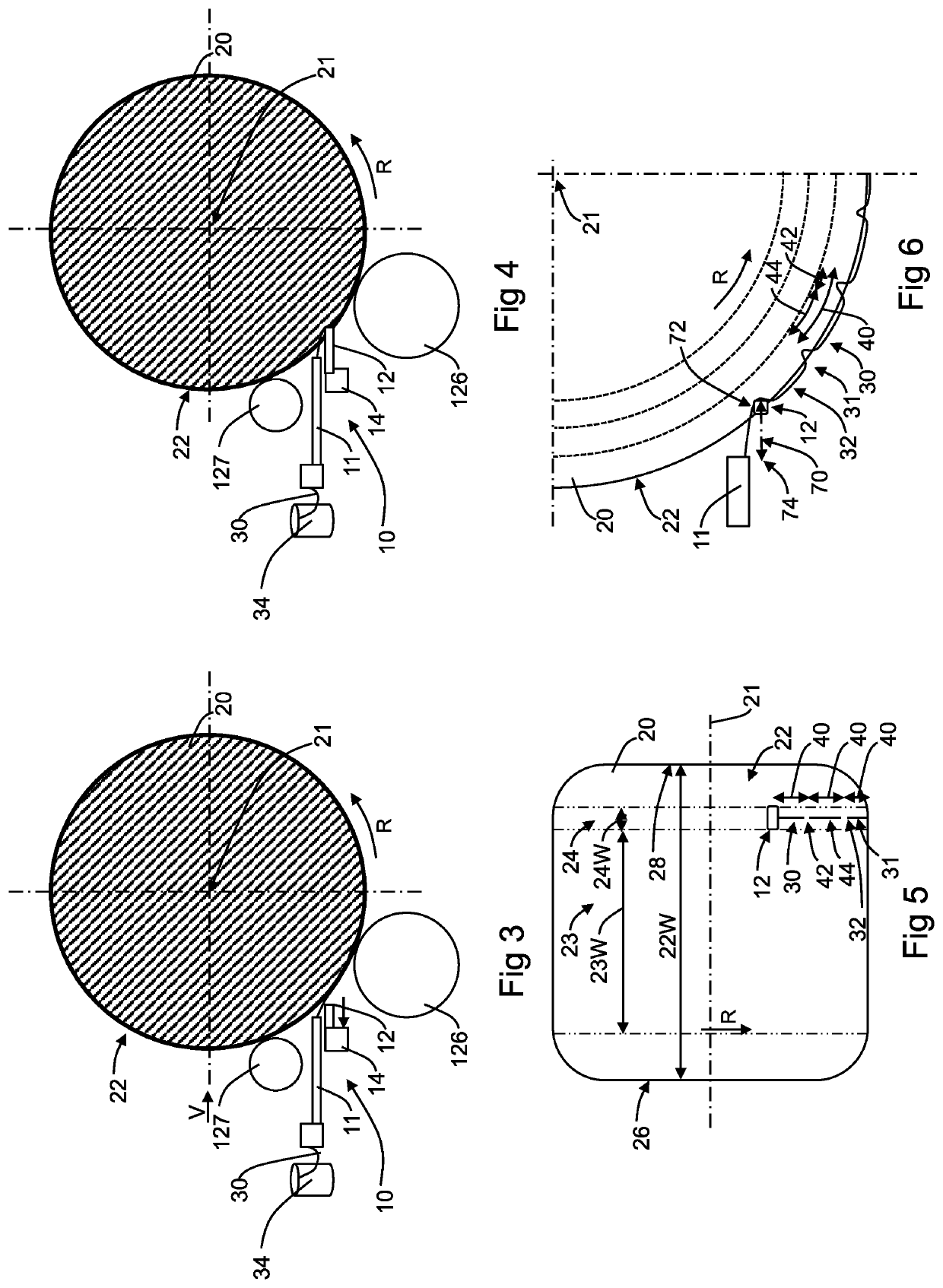
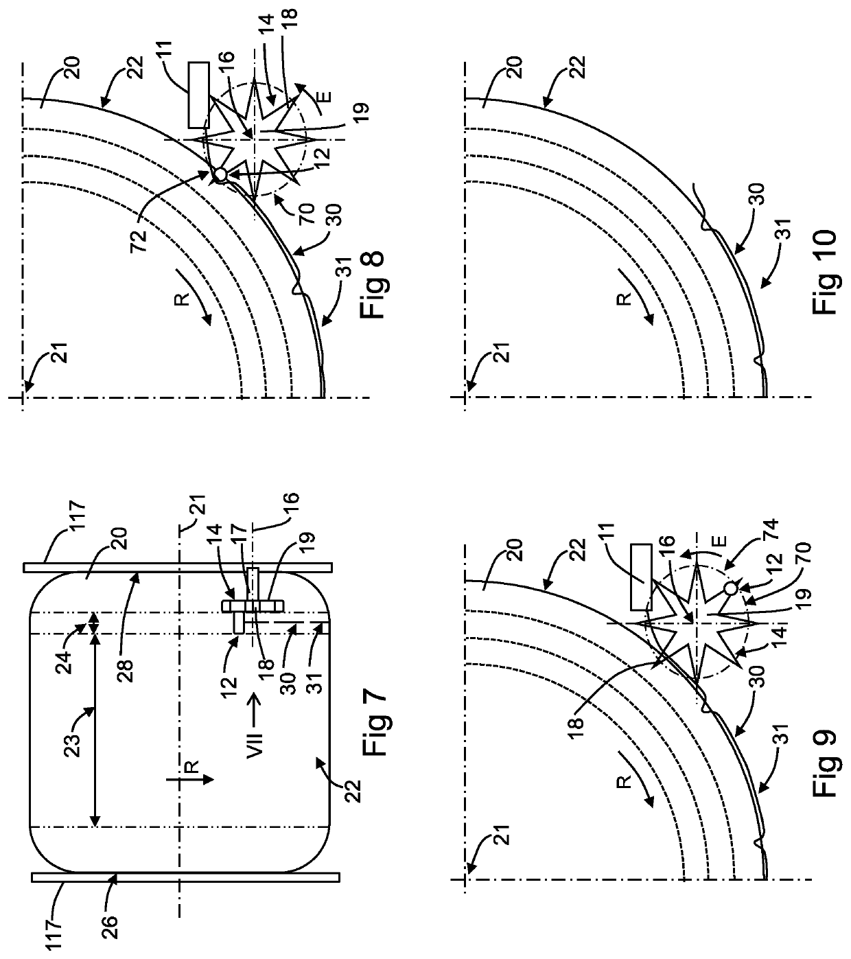
[0073]FIG. 1 schematically shows an embodiment of an agricultural round baler 1, which, when performing a baling operation, is pulled by an agricultural tractor (not shown) along a windrow of cut crop material while generally moving along a movement direction D. Round baler 1 for this purpose comprises a tongue 118 extending from the forward portion of main frame 114 for conventional connection to an agricultural tractor. The embodiment of the round baler 1 shown in FIG. 1, is generally referred to as a fixed chamber round baler 1 having a wrapping assembly 10 for wrapping the outer circumferential surface 22 of a completed bale 20 formed in the round baler 1. More particularly, the bale wrapping assembly 10 of the baler 1 is of the type, which is generally referred to as a twine wrapping assembly, and which is configured to wrap one or more twines around the outer circumferential surface 22 of the completed bale 20 as will be explained in further detail below. It is clear that alth...


PUM

PropertyMeasurementUnit
lengthaaaaaaaaaa
distanceaaaaaaaaaa
distanceaaaaaaaaaa

Abstract

The bale wrapping assembly for a round baler includes at least one twine inserter coupled to a drive. The drive is configured to drive the at least one twine inserter along a movement trajectory to intermittently introduce one or more twines into an outer circumferential surface of a completed bale. The one or more twines are positioned at the at least one twine inserter.

Description

[0001]This application claims priority to Belgium Application BE2014 / 0739 filed Sep. 26, 2014, which is incorporated herein by reference in its entirety.FIELD OF THE INVENTION[0002]The invention concerns a bale wrapping assembly for a round baler and a method of operating a bale wrapping assembly. More particularly a bale wrapping assembly for a round baler of the type that wraps twine around a completed bale during a wrapping operation.BACKGROUND OF THE INVENTION[0003]It is generally known to execute a bale wrapping operation after a completed bale has been formed in the bale forming chamber of a round baler. During such a wrapping operation a suitable wrapping material is applied to the outer circumferential surface of the completed bale. Such wrapping material could for example be a suitable net, a suitable plastic layer, one or more twines, etc. The invention concerns a bale wrapping assembly suitable for applying twines during such a wrapping operation to the outer circumferent...

Claims


Application Information

Patent Timeline
Patent Type & Authority Patents(United States)
IPC IPC(8): A01F15/07A01F15/14B65B11/04
CPCA01F15/0715A01F15/141B65B11/04A01F2015/0745
Inventor DE BAERE, FREEKVAN GIEL, MICHAEL
Owner BLUE LEAF I P INC
Learn More