
Part display apparatus, electronic music apparatus, and part display method

a display apparatus and electronic music technology, applied in the direction of instruments, cathode-ray tube indicators, transducer details, etc., can solve the problems of lack of convenience and difficulty in ensuring the display region corresponding to all parts of the display screen, so as to achieve convenient checking, sacrificing convenience, and ensuring the effect of convenien

Active Publication Date: 2021-11-30
YAMAHA CORP
View PDF6 Cites 0 Cited by
  • Summary
  • Abstract
  • Description
  • Claims
  • Application Information

AI Technical Summary

Benefits of technology

The present invention provides a part display apparatus that allows easy checking of parts information without sacrificing convenience, even when there are a large number of parts. Additionally, the invention is also applicable to an electronic music apparatus that includes this part display apparatus.

Problems solved by technology

However, if the number of parts increases, it is difficult to ensure display regions corresponding to all parts on the display screen.
However, in this case, it is necessary to switch the display in order to check the information on a part that has not been selected, which lacks convenience.

Method used


Image

  • Part display apparatus, electronic music apparatus, and part display method
  • Part display apparatus, electronic music apparatus, and part display method
  • Part display apparatus, electronic music apparatus, and part display method

Examples


first embodiment

(1) First Embodiment

(1-1) Configuration of Electronic Music Apparatus

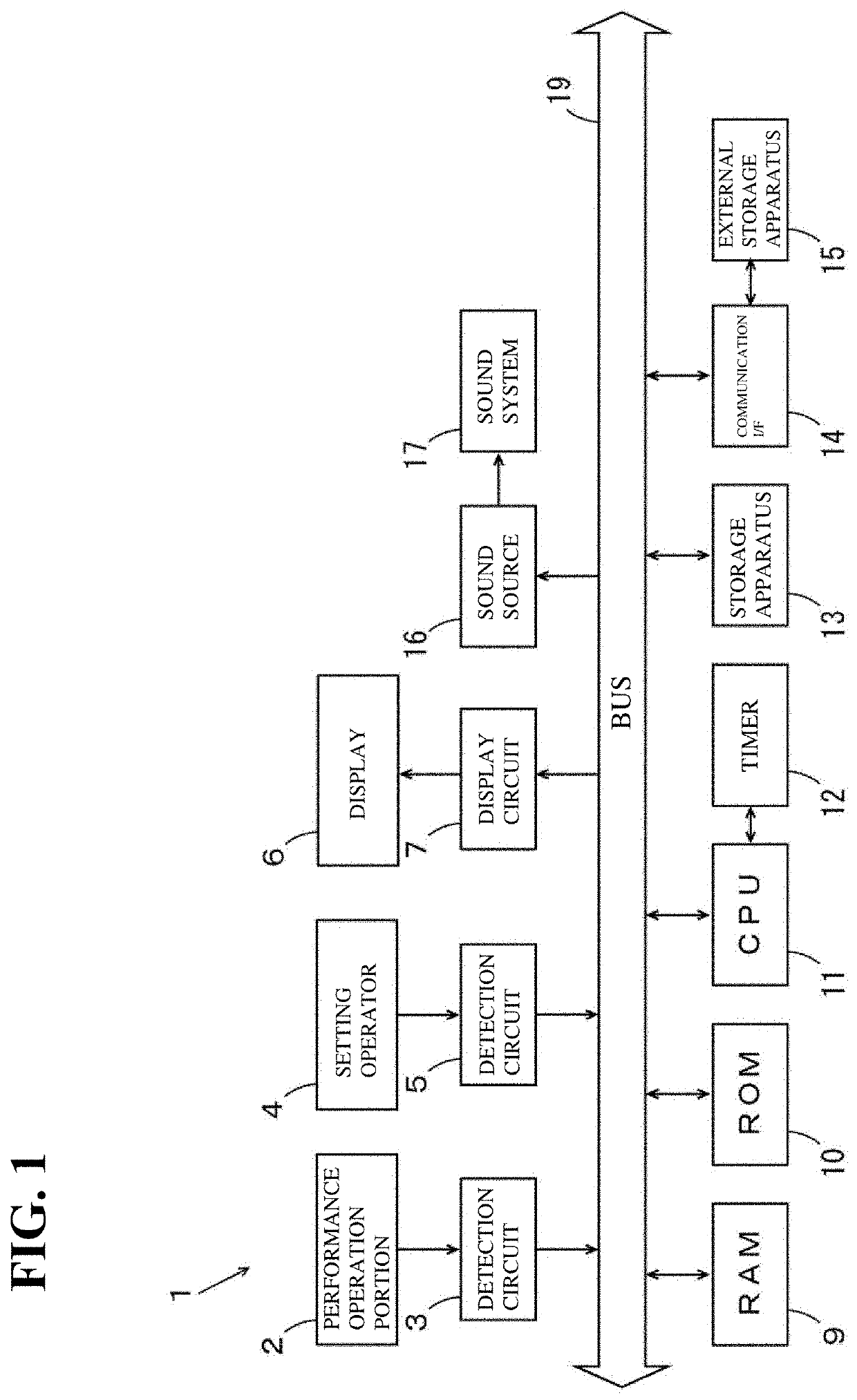
[0045]FIG. 1 is a block diagram showing a configuration of an electronic music apparatus including a part display apparatus according to the present embodiment. The electronic music apparatus 1 of FIG. 1 is an electronic keyboard instrument that can be used to perform and create a musical piece. The electronic music apparatus 1 includes a performance operation portion 2, a detection circuit 3, a setting operator 4, a detection circuit 5, a display 6, and a display circuit 7.

[0046]In the present example, the performance operation portion 2 is a keyboard including multiple keys. The keys are examples of pitch designators. The performance operation portion 2 is connected to a bus 19 via the detection circuit 3, and performance data obtained based on a performance operation of a user is input using the performance operation portion 2. The performance data includes pitch information and velocity information. The setting...

second embodiment

(2) Second Embodiment

(2-1) Overall Configuration of Acoustic System

[0117]FIG. 13 is block diagram showing a configuration of an acoustic system 1000 including the part display apparatus according to the present embodiment. The acoustic system 1000 of FIG. 13 includes multiple acoustic devices a to h and a controller 1001 connected to the acoustic devices a to h. The acoustic devices a to h have a communication function and can communication with another device such as the controller 1001, which also has a communication function. The controller 1001 sets the setting information of the acoustic devices a to h and controls the operations of the acoustic devices a to h accordingly. The setting information in this context relates to, for example, the name, model name, on / off state, equalizer, volume, and the like of the device. These pieces of setting information can be set as appropriate by the user operating the controller 1001. The acoustic system 1000 further includes a distribution ...


PUM


Abstract

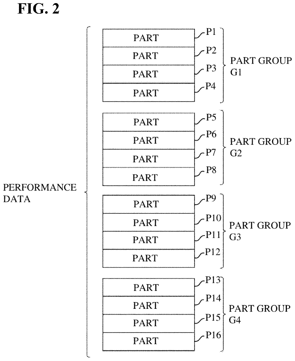
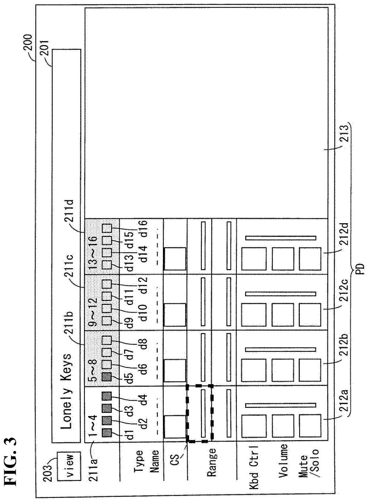
Provided is a part display apparatus. The part display apparatus includes: a tab display unit configured to display a plurality of tabs respectively corresponding to a plurality of part groups; a digest information display unit configured to display, in each tab of the plurality of tabs, digest information of each part of the part group corresponding to that tab; a tab selection reception unit configured to receive selection of any one of the plurality of tabs; and a detailed information display unit configured to display a part detail screen including detailed information of the part group corresponding to the selected tab.

Description

CROSS REFERENCE TO RELATED APPLICATIONS[0001]The present application is a continuation application of International Application No. PCT / JP2018 / 1372, filed Jan. 18, 2018, which claims a priority to Japanese Patent Application No. 2017-6949, filed Jan. 18, 2017. The contents of these applications are incorporated herein by reference in their entirety.FIELD OF INVENTION[0002]The present invention relates to a part display apparatus, an electronic music apparatus, and a part display method.BACKGROUND[0003]In an electronic musical apparatus such as an electronic musical instrument and a mixer, information related to multiple parts is displayed on a display. A DJ (disc jockey) system described in JP 478149B (hereinafter referred to as “Patent Literature 1”) includes a DJ controller and a personal computer. The DJ controller includes the function of a mixer and can perform operation on audio signals assigned to four channels (parts). A DJ application is installed in a personal computer. Th...

Claims


Application Information

Patent Timeline
Patent Type & Authority Patents(United States)
IPC IPC(8): G06F3/048G06F3/02G06F3/14
CPCG06F3/048G06F3/0219G06F3/1446H04R3/00G10H1/18G09G5/14G09G5/003
Inventor SASAKI, NAOYAOHNO, TAKUNISHIMURA, AKIKO
Owner YAMAHA CORP
Learn More