Commissioning in multi-hop networks by using a single-hop connection

a multi-hop network and single-hop technology, applied in the field of wireless network commissioning, can solve the problems of security risk and disadvantages of existing zigbee commissioning methods

Active Publication Date: 2021-11-30
SIGNIFY HLDG BV
View PDF13 Cites 109 Cited by
  • Summary
  • Abstract
  • Description
  • Claims
  • Application Information

AI Technical Summary

Benefits of technology

[0008]It is an object of the present invention to provide a more reliable and / or more user-friendly commissioning approach.
[0010]Accordingly, an added point-to-point connection of a single-hop technology provides a combo network device with an enhanced user interface to an external commissioning device (e.g. tablet, smartphone, etc. as master device). This point-to-point connection can be used to exchange information required for the joining procedure and to inform the combo device that it should search for and join a (specific) multi-hop network. This allows the user to seamlessly transfer from controlling the combo device via the point-to-point connection to controlling the combo device via the multi-hop network via a bridge device, without running the risk of unnecessarily looking for open networks, having to look up and enter an access or security code or bringing the combo device close to the bridge device, and whilst maintaining a secure and reliable setup.
[0012]According to a first option, the trigger unit may be adapted to initiate the joining procedure in response to an input operation at a user interface. Thereby, a user can trigger a joining procedure for the network node by a simple input operation at the commissioning device, e.g., by an app of a smartphone or tablet or the like.
[0015]According to an alternative fourth option which can be combined with the first or second option, the single-hop communication unit may be used for reading a commissioning code from the network node and the network interface may be used for forwarding the read commissioning code to the bridge device and for instructing the bridge device to initiate a search for new devices in the multi-hop network based on the commissioning code. The bridge device may be adapted to send the command containing the commissioning code to network nodes of the multi-hop network. In this case, the joining control unit of the network node may be adapted to compare an own commissioning code, stored in the parameter storage unit, with the commissioning code received from the multi-hop network together with a command for resetting to a factory new state and to initiate a reset to a factory new state and the joining procedure if the own commissioning code matches with the received commissioning code. This option is advantageous in that the network node is capable of exposing its commissioning code (e.g. a unique secret which may be provided via a GATT characteristic) via the point-to-point connection to the commissioning device, so that the commissioning device can forward it to the bridge device which can force the network node into the commissioning mode.
[0016]According to an alternative fifth option which can be combined with the first or second option, the single-hop communication unit may be used for providing network information required for joining the multi-hop network to the network node. Then, the joining control unit of the network node may be adapted to initiate the joining procedure of the multi-hop network in response to the receipt of required network information of the multi-hop network via the single-hop communication unit. This option is advantageous in that additional network information is directly provided to the network node by the commissioning device, so that the bridge device does not need to open the multi-hop network.

Problems solved by technology

However, existing ZigBee commissioning methods have disadvantages.
For a factory-new device, there is a security risk when automatically searching for and joining a ZigBee network.

Method used


Image

  • Commissioning in multi-hop networks by using a single-hop connection
  • Commissioning in multi-hop networks by using a single-hop connection
  • Commissioning in multi-hop networks by using a single-hop connection

Examples


first embodiment

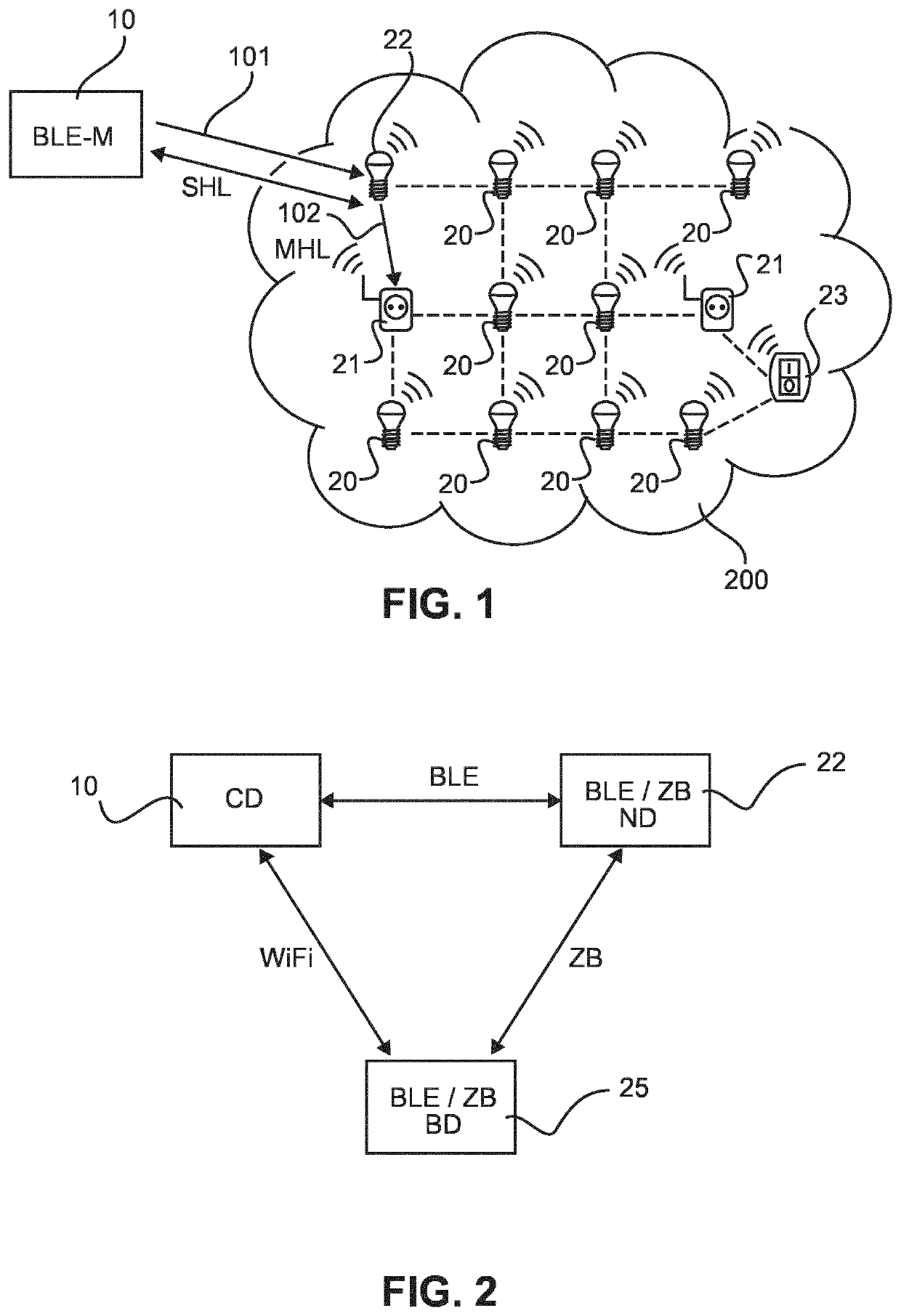
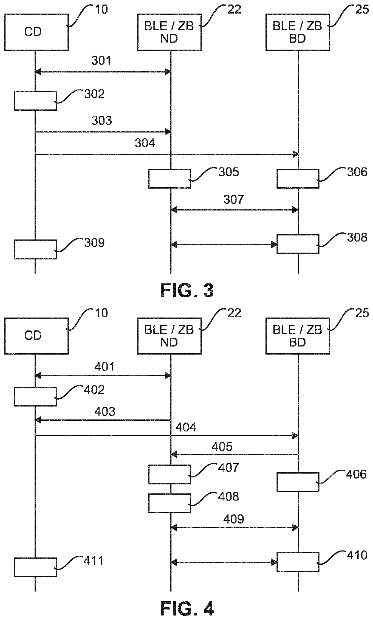
[0038]FIG. 3 shows a signaling and processing diagram of a joining procedure where the external commissioning device (CD) 10 is used as BLE master and provides a user interface for a new combo radio device (ND) 22 which is used as BLE slave with additional ZigBee (ZB) communication unit. In FIG. 3 as well as the remaining FIGS. 4 and 5, horizontal arrows indicate signaling between devices indicated by boxes at the top of the diagrams and the blocks below the boxes of the respective devices indicate processing steps or procedures of the device located above the respective block. The time proceeds in the vertical direction from the top to the bottom of the diagrams.

[0039]In the following, a joining procedure according to the first embodiment is described with reference to FIG. 3.

[0040]To allow a new combo radio device 22 (e.g. a lamp or luminaire) to join a ZigBee network via BLE it needs to offer additional functionality via its BLE interface (next to the basic light control functio...

second embodiment

[0048]FIG. 4 shows a signaling and processing diagram of a joining procedure where the new combo radio device 22 is adapted to expose a unique secret information (such as the 6-digit hexadecimal number or so-called “install code”) via a GATT characteristic (“ZigBee commissioning code”) or other appropriate means and provide that secret to the bridge device 25, which can use it to force the new combo radio device 22 into a commissioning mode, or allow combo radio device 22 to join the network.

[0049]In step 401, the commissioning device 10 of the user is paired and bonded via BLE to the new combo radio device 22 that supports both ZigBee and BLE.

[0050]If the user now wants to add this new combo radio device 22 to a ZigBee network of the bridge device 25, it triggers this action in an app of the commissioning device 10 in step 402. Alternatively, the app could detect presence of the bridge device 25 and could automatically trigger the action to add the new combo radio device 22 to the...

third embodiment

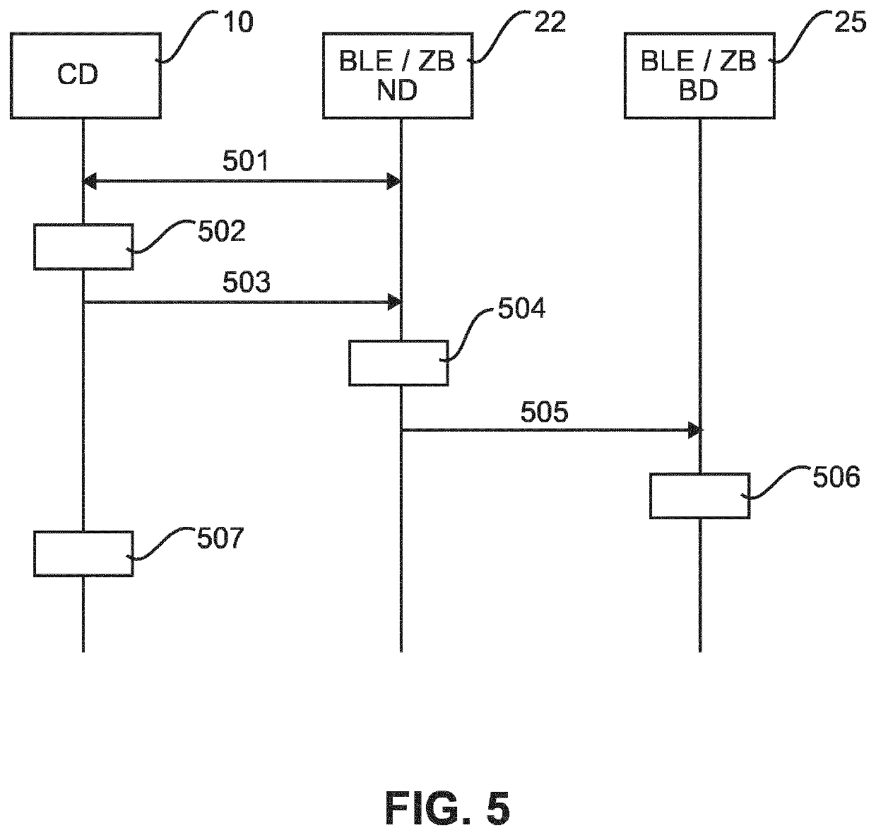
[0060]FIG. 5 shows a signaling and processing diagram of a joining procedure where additional information is provided to the new combo radio device 22 such that the bridge device 25 does not need to open the network.

[0061]In step 501, the commissioning device 10 of a user is paired via BLE to the new combo radio device 22 that supports both ZigBee and BLE.

[0062]If the user now wants to add this new combo radio device 22 to the ZigBee network of the bridge device 25, it triggers this action in an app of the commissioning device 10. Alternatively, the app of the commissioning device 10 could detect presence of the bridge device 25 and could automatically trigger the action to add the new combo radio device 22 to the ZigBee network of the bridge device 25.

[0063]Once the “add lamp to bridge” action has been triggered in step 502, the app of the commissioning device 10 provides in step 503 network information details (such as channel, PAN ID and network key, which could be received e.g....


PUM


Abstract

The present invention relates to methods and apparatuses for controlling commissioning of a network device (22) in a multi-hop network, e.g., ZigBee network, (200) of a multi-hop technology, wherein the network device (22) is a combo network device with a single-hop communication unit of a single-hop technology, e.g., Bluetooth Low Energy (BLE), for establishing a point-to-point connection and a multi-hop communication unit of the multi-hop technology for communicating with other network devices (20) of the multi-hop network in the multi-hop network (200). The single-hop connection of the network device (22) for commissioning allows seamless transfer from controlling the network device (22) via the single-hop network to controlling the network device (22) via the multi-hop network via a bridge device (25), without running the risk of unnecessarily looking for open networks, having to look up and enter an access key or bringing the network device (22) close to the bridge device (25), and whilst maintaining a secure setup.

Description

CROSS-REFERENCE TO PRIOR APPLICATIONS[0001]This application is the U.S. National Phase application under 35 U.S.C. § 371 of International Application No. PCT / EP2018 / 073006, filed on Aug. 27, 2018, which claims the benefit of European Patent Application No. 17189625.1, filed on Sep. 6, 2017. These applications are hereby incorporated by reference herein.FIELD OF THE INVENTION[0002]The invention relates to the field of commissioning of network devices in wireless networks, such as—but not limited to—ZigBee networks, for use in various different applications for home, office, retail, hospitality and industry.BACKGROUND OF THE INVENTION[0003]ZigBee networks represent another type of a low-power / low-cost wireless networks which allow multi-hop communication among devices in a mesh topology. ZigBee devices offer reduced power consumption and cost, together with mesh networking capability, which make them suitable for use in large-scale deployments. Examples of application of ZigBee mesh n...

Claims


Application Information

Patent Timeline
Patent Type & Authority Patents(United States)
IPC IPC(8): H04W84/18H04L12/751H04W40/28H04L45/02
CPCH04W84/18H04L45/02H04W40/28Y02D30/70
Inventor MICHIELSEN, ROBINROZENDAAL, LEENDERT TEUNISDRIESEN, BAS
Owner SIGNIFY HLDG BV
Why Eureka
Try Eureka