Multi-conductor rotary connector

a rotary connector, multi-conductor technology, applied in the direction of coupling contact members, coupling device connections, current collectors, etc., can solve the problems of prone to very low durability, inability to unitize plastic molding, and easy to break and/or permanent damage, etc., to achieve high durability, resist fatigue failure, and withstand intense vibrations

Active Publication Date: 2022-01-04
RAMPART PROD LLC
View PDF18 Cites 4 Cited by
  • Summary
  • Abstract
  • Description
  • Claims
  • Application Information

AI Technical Summary

Benefits of technology

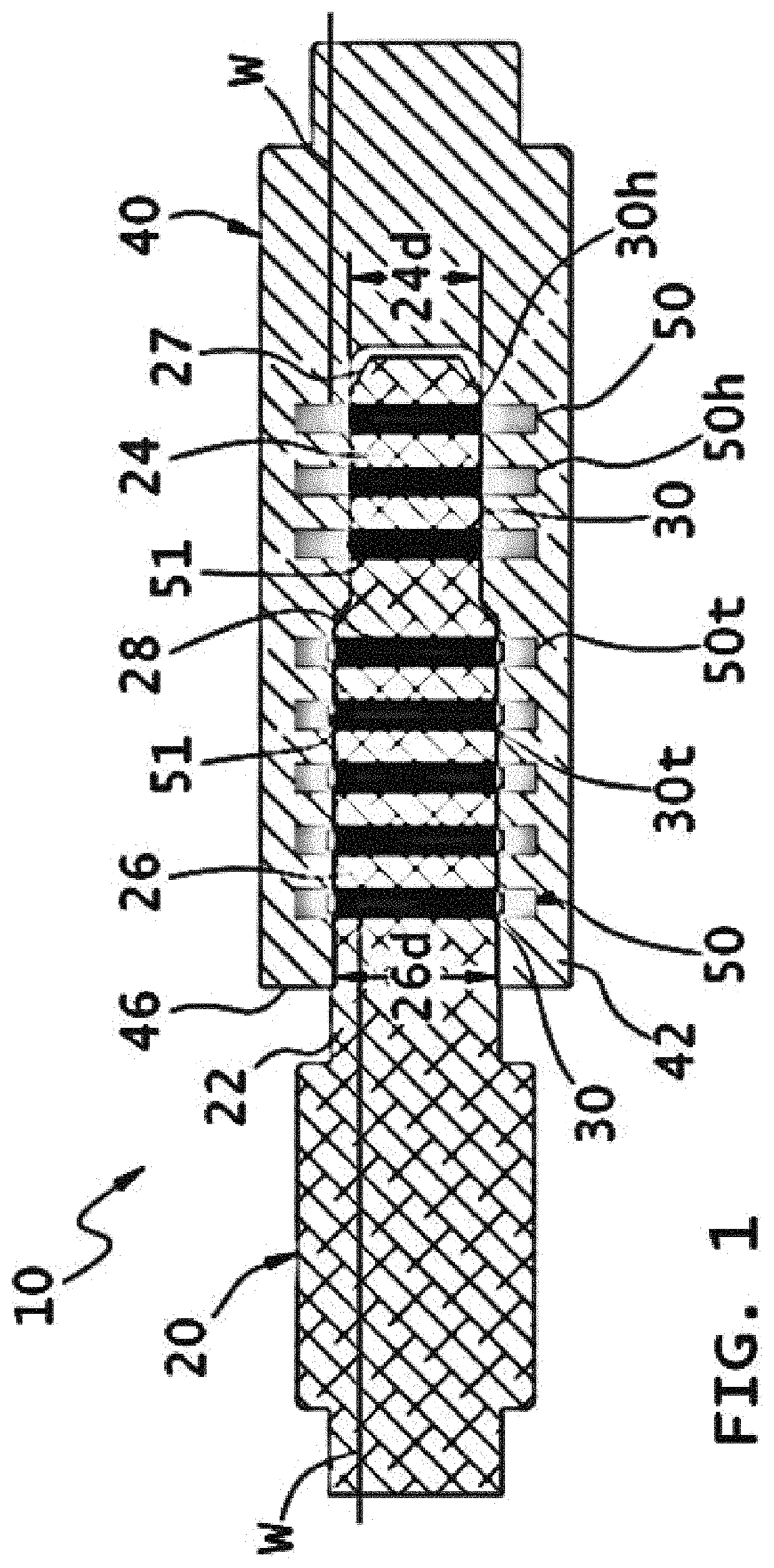
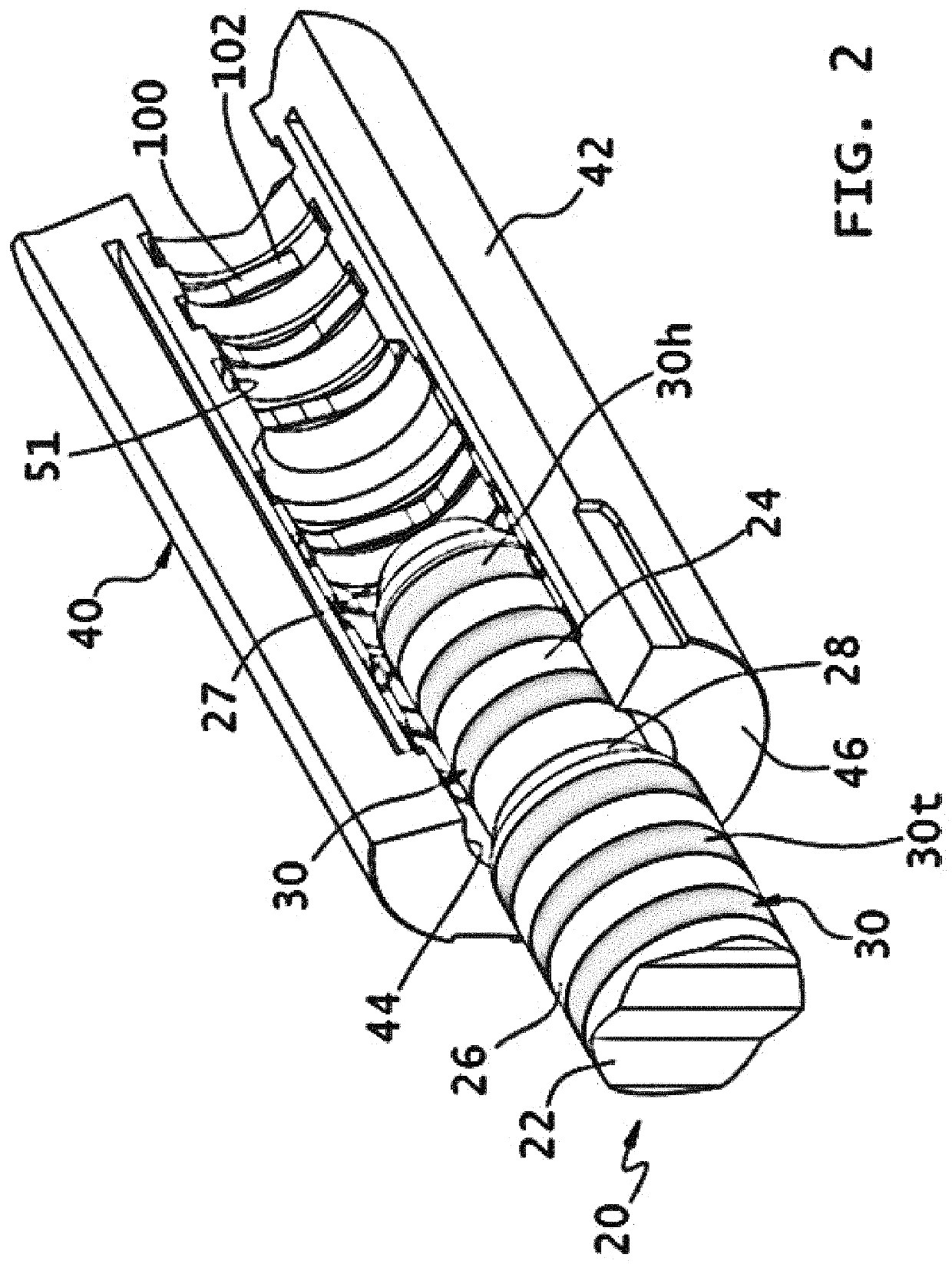
[0011]The preferred embodiments of the invention provide a rotary connector having a plug and a receptacle with high durability during operation, in addition to having very low likelihood of damage during maintenance. In the rare event that a contact is damaged, the contact is replaceable. The rotary connector has very high shock and vibration tolerance making it well-suited for use in extreme and difficult environments. The preferred embodiments provide a connector having high electrical current capacity. The rotary connector is radially and axially compact, thus allowing for a smaller form factor connector. At least some of the embodiments allow for unitized molded assembly.

Problems solved by technology

Some shortcomings with the O-ring energized multi-leaf spring contact are: the thin metal leaves are fragile and break easily; the thin metal leaves are easily snagged during cleaning with rags, etc. thus causing breakage and / or permanent damage; low conductor cross-sectional area limiting electrical current capacity; the O-ring energizers are subject to compression set at elevated temperatures; does not allow for unitized plastic molding around contacts due to many leak pathways; and not axially compact.
Although canted coil springs are easily replaced, they are suspect / prone to having very low durability—especially in harsh operating conditions such as high temperature, high pressure environments, or when subjected to vibrational forces, or cyclical loading—experienced in many applications where rotary connectors are used.
The canted coil spring often cracks during operation and is prone to getting snagged and dislodged when cleaning the connector.
The canted coil spring may become dislodged during connection or disconnection of the coupler or due to allowable manufacturing tolerances of the connector which may result in slight misalignment of the mating connectors.
Pogo pins are subject to movement during shock and vibration thus causing potential electrical signal issues and mechanical damage.
Pogo pins are prone to shearing during mating of connectors thus causing permanent damage.
Other disadvantages with spring-loaded pogo pin contacts are: pogo pins are not replaceable; no unitized plastic molding around contacts is possible due to plastic invasion into back side of the pogo canister; and not radially or axially compact so connectors cannot be as compact.

Method used


Image

  • Multi-conductor rotary connector
  • Multi-conductor rotary connector
  • Multi-conductor rotary connector

Examples


Embodiment Construction

[0033]It should be understood at the outset that although illustrative implementations of one or more embodiments are described below, the disclosed assemblies, systems and methods may be implemented using any number of techniques, whether currently known or not yet in existence. The disclosure should in no way be limited to the illustrative implementations, drawings, and techniques described below, but may be modified within the scope of the appended claims along with their full scope of equivalents.

[0034]The following brief definition of terms shall apply throughout the application:

[0035]The phrases “in one embodiment,”“according to one embodiment,” and the like generally mean that the particular feature, structure, or characteristic following the phrase may be included in at least one embodiment of the present invention, and may be included in more than one embodiment of the present invention (importantly, such phrases do not necessarily refer to the same embodiment);

[0036]If the...


PUM


Abstract

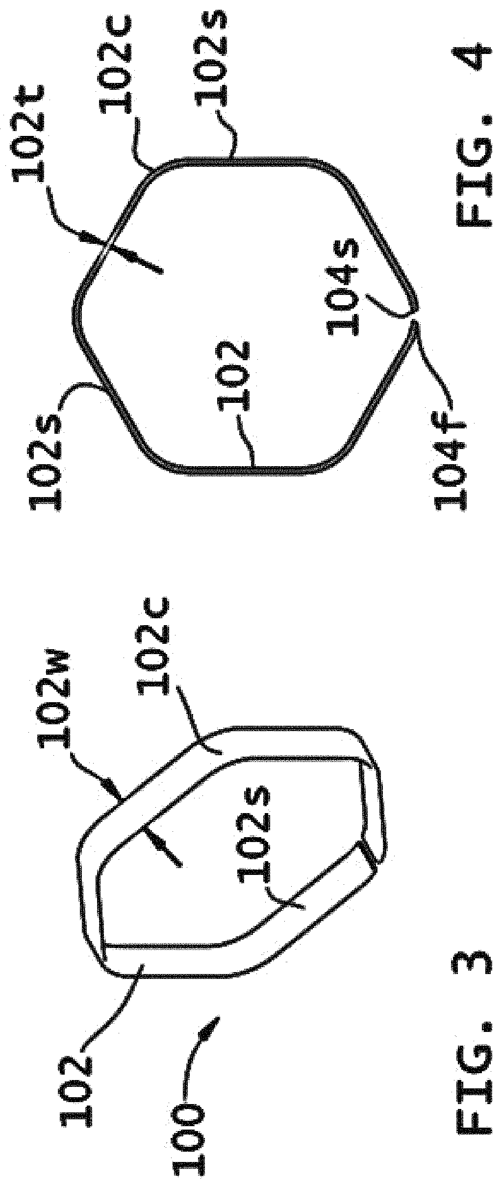
An electrical connector comprising a plug arranged and designed to connect to a receptacle. The plug includes an electrically-insulating body, a conductor ring, and a conductive member connected to the plug conductor ring. The receptacle includes an electrically-insulating body, a conductor ring having an axial inner bore and an annular groove facing radially inward, a conductive member connected to the receptacle conductor ring, and an electrically-conductive contact having a generally annular profile, at least a portion of the electrically-conductive contact received in and contacting the annular groove and at least a portion of the electrically-conductive contact not received in the annular groove. Upon insertion of the plug into the receptacle and substantially radially aligning the plug and receptacle conductor rings, the electrically-conductive contact is elastically deformed and provides electrical contact between the plug conductor ring and the receptacle conductor ring.

Description

CROSS-REFERENCE TO RELATED APPLICATIONS[0001]This application claims the benefit of U.S. Provisional Application Ser. No. 62 / 842,841, filed on May 3, 2019, entitled “Multi-Conductor Rotary Connector.” Applicant incorporates by reference herein Application Ser. No. 62 / 842,841 in its entirety.BACKGROUND OF THE INVENTION1. Field of the Invention[0002]The present invention relates generally to electrical, multiple conductor rotary connectors, and more specifically to the contacts for electrical, multiple conductor rotary connectors.2. Description of the Related Art[0003]Electrical rotary connectors typically include a male assembly and a female assembly that engage one another and permit rotation of the male and female assemblies with respect to one another. Oftentimes, the joining of the male and female assemblies will have relative rotation as a result of threaded members. Sometimes it is desirable, that upon mating of the male and female assemblies to one another, for relative rotati...

Claims


Application Information

Patent Timeline
Patent Type & Authority Patents(United States)
IPC IPC(8): H01R13/187H01R39/64H01R13/10H01R13/17
CPCH01R13/187H01R13/10H01R13/17H01R39/64H01R13/111H01R24/58F16F1/025H01R13/5202
Inventor CARTER, SEAN WCZUPPON, MICHAEL ABESHOORY, EDWARD J
Owner RAMPART PROD LLC
Why Eureka
Try Eureka