
Tire pressure control system and components

a technology of control system and components, applied in the direction of positive displacement liquid engine, piston pump, liquid fuel engine, etc., can solve the problems of increasing maintenance cost, corresponding construction expense, and long line distances of pressurized medium lines, so as to increase the driving safety and driving comfort of the vehicle, and the data rate is higher. , the effect of increasing the data quality

Active Publication Date: 2022-01-18
ILLINOIS TOOL WORKS INC +1
View PDF27 Cites 0 Cited by
  • Summary
  • Abstract
  • Description
  • Claims
  • Application Information

AI Technical Summary

Benefits of technology

[0118]Each respective lubricant depot 112 can be provided with a suitable support material or a suitable support matrix for the lubricant. The support matrix can be of a metallic type or can also be embodied by means of a foam-like or foamed material. In general, the support matrix can be embodied as porous in order to be able to release lubricant in as defined a way as possible over a long period of time. Each respective lubricant depot 112 has no disadvantageous effects—or only insignificant ones—on the guidance behavior of the piston assembly 86. This is particularly due to the fact that the piston assembly 86 is a rigid apparatus.
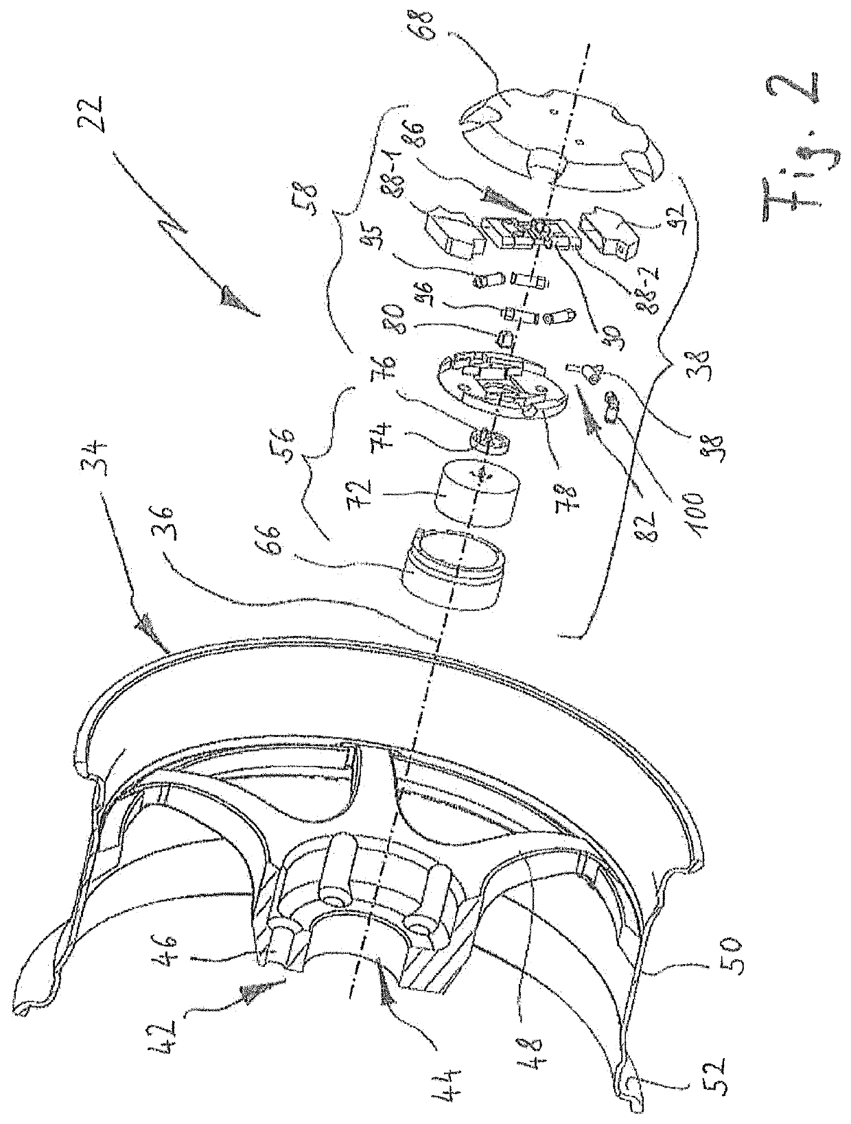
[0119]Check valves 95 and 96 that produce a coupling with the working chambers (or cylinder chambers) 94-1 and 94-2 are also symbolically depicted in FIG. 6. Intake valves are labeled with the reference numeral 95 and exhaust valves are labeled with the reference numeral 96. In alternating fashion, one of the working chambers 94-1 and 94-2 is always in either an intake mode or a compression mode when the piston assembly 86 is being moved back and forth in the reciprocation direction 102. In the example shown in FIG. 6, unlike in the embodiment in FIGS. 2 through 5, the intake valves 95 and the exhaust valves 96 are embedded in the cylinder, thus permitting a more compact design of the compressor unit 38.
[0120]FIG. 7 shows another embodiment of the compressor unit 38, which differs from the embodiment in FIGS. 2 through 5 and the example in FIG. 6 with regard to the placement and type of the intake valves. In this case, the intake valves 95 are positioned on the piston assembly 86 itself, specifically in the form of leaf valves embodied on the end walls 116 of the piston sections 88-1 and 88-2. These leaf valves fold open, as indicated by the arrows shown in FIG. 7, during an expansion movement or intake stroke of the relevant piston section 88 and thus allow pressurized medium to flow into the associated working chamber 94. In a subsequent compression movement or compression stroke of the relevant piston section 88 in the opposite direction, the leaf valves fold closed again and prevent a further intake of pressurized medium into associated working chamber 94. As compared to check valves, leaf valves have the advantage that they open more quickly during an intake stroke and as a result, more air can travel into the working chamber 94. It is thus possible to increase the volumetric displacement of the compressor unit 38.
[0121]Another difference that the embodiment shown in FIG. 7 has in comparison to the examples shown in FIGS. 2 through 5 and FIG. 6 lies in the fact that the piston assembly 86 embodied as a double piston is composed of one piece. Instead connecting the piston sections 88-1 and 88-2 to each other by means of an interposed drive element 90, the double piston 86 shown in FIG. 7 is composed of one piece, for example made of a metal material. In the region of the end walls 116, sealing lips 118 and 120 are positioned spaced apart from each other, order to ensure a seal relative to the respective cylinder 92. In this case, the lubricant depot 112 is formed between the spaced-apart sealing lips 118 and 120. It is also clear that the use of a slider 80 can be eliminated and the eccentric coupling 76 can basically also travel in the sliding guide 104 without a slider. In order to minimize the friction between the eccentric coupling 76 and the sliding guide 104, the eccentric coupling 76 eccentric coupling be supported on the drive shaft 74 in rotary fashion.
[0122]FIGS. 8a and 8b show another exemplary embodiment of the compressor unit 38 in which the installation space requirement is reduced by embodying the cylinders 92 by means of the module housing 64 itself. FIG. 8a shows the exemplary embodiment in an exploded view, while FIG. 8b shows the compressor unit 38 in an assembled state. In order to further reduce the space requirement, the intake valves 95 and exhaust valves 96, similar to the exemplary embodiment in FIG. 6, are embedded in the respective cylinders 92; in this example, however, they are embodied as leaf valves.
[0123]FIG. 9 shows a schematic depiction of another embodiment in which the intake valves 95 are embodied in the respective piston section 88 in such a way that during an intake stroke of the relevant piston section 88, the respective intake valve 95 is forced open by its movement. In the example shown, the intake valves 95 are each embodied between the piston sections 88 and the associated cylinders 92. The intake valves 95 include a sealing element 122 that is mounted in a resilient fashion to the end wall 116 of the respective piston section 88 (e.g. by means of a compression spring), which sealing element is pressed against a pressurized medium inlet opening positioned in the associated cylinder 92 and closes this opening until it is moved away from the pressurized medium inlet opening during an intake stroke. In this example, the opening of the intake valves 95 is therefore produced by the movement of the piston itself in that the respective sealing element 122 is briefly pulled away from the pressurized medium inlet opening by the relevant piston section 88 and uncovers it. Since the opening and closing of the intake valves 95 is controlled by the movement of the piston, this arrangement can also be referred to as “piston-controlled intake valves.” The opening of an intake valve 95 in this case is independent of a vacuum produced in the associated working chamber 94 by the intake stroke. In comparison to conventional check valves, the intake valve can therefore be opened more quickly and it is thus possible to achieve an improved intake volume with a higher delivery capacity overall. FIG. 9 also shows that the pressurized medium inlets can be provided with filters 124 for filtering the aspirated pressurized medium.

Problems solved by technology

One basic disadvantage lies in the fact that the pressurized medium lines must bridge very long line distances.
This results in a corresponding construction expense and an increased maintenance cost.
Central compressed air supply units are also susceptible to leaks, in particular those that are caused by external stresses.
It is also particularly difficult to achieve a reliable, durably functional embodiment of the rotary feed-throughs, which are exposed to a stress by the wheels that rotate while driving.
The aspects enumerated above result in an increased production cost, which is accompanied by a high installation expense (in original equipment installed by the vehicle manufacturer) or retrofitting expense (in the case of aftermarket installation).
Some of the above-mentioned problems, particularly with regard to the long-term reliability of the systems, can only be controlled with difficulty.
The prevalence of such systems is thus very limited.

Method used


Image

  • Tire pressure control system and components
  • Tire pressure control system and components
  • Tire pressure control system and components

Examples


example 1

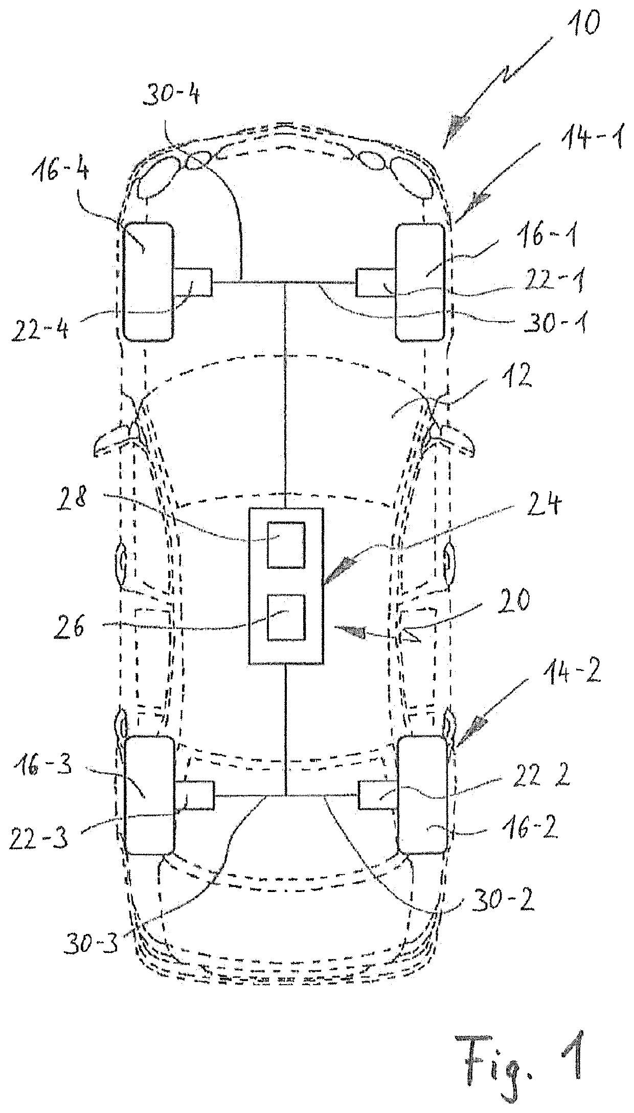
[0159]A decentralized integrated pressurized medium supply device, in particular for supplying compressed air for a vehicle wheel,[0160]having a rotatably supported vehicle wheel that includes a tire that can be inflated with a pressurized fluid,[0161]having a compressor unit, in particular an electric motor-driven compressor unit, which can be mounted on the vehicle wheel and, together with the vehicle wheel, can be mounted in rotary fashion on a wheel carrier of a vehicle,

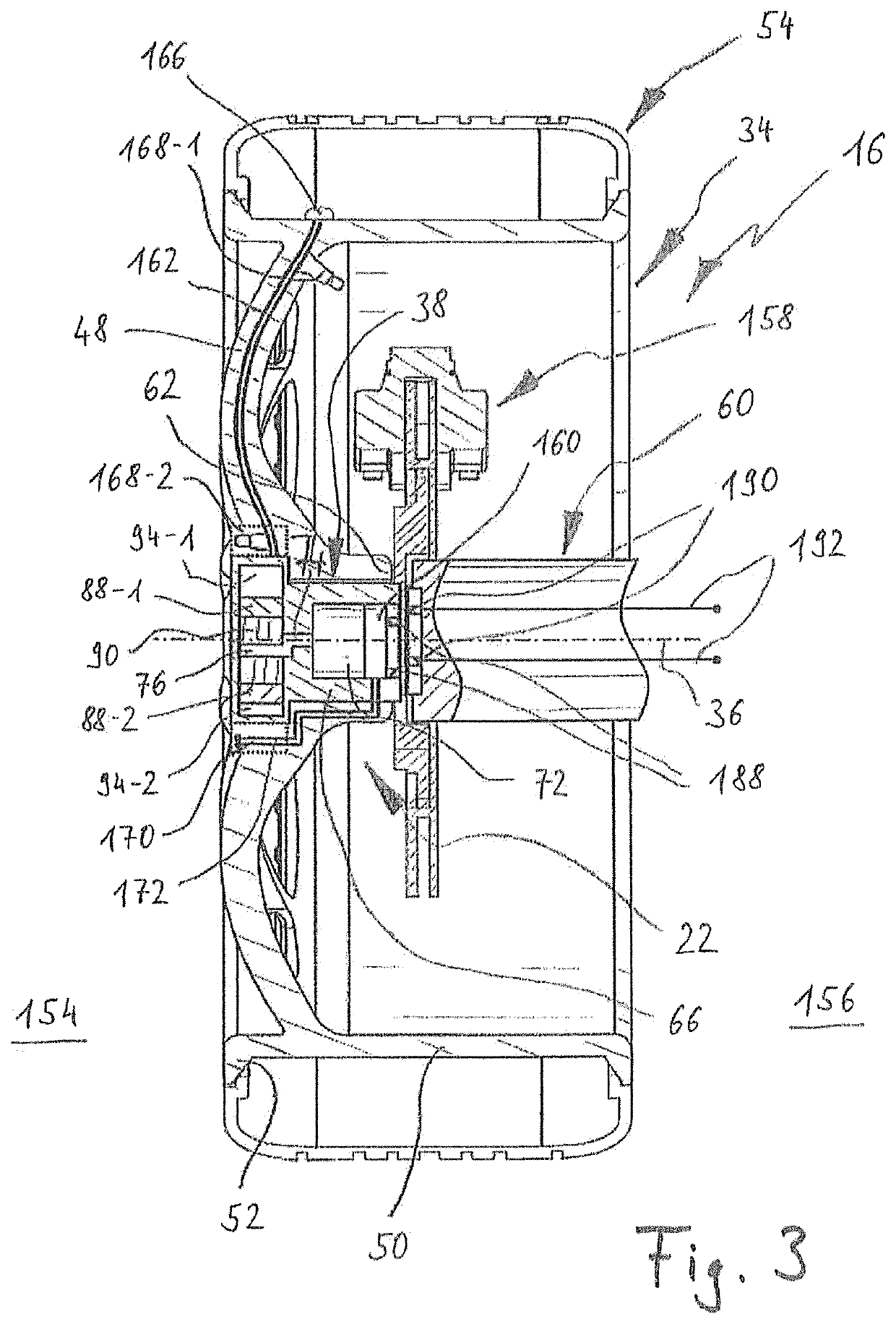
[0162]in which the compressor unit includes a compressor and in an assembled state, is positioned in a central region of the vehicle wheel, between a rim of the vehicle wheel and a wheel hub, and

[0163]the compressor can be supplied with energy via the wheel carrier of the vehicle in order, in an active operating state, to exert pressure on a pressurized fluid, in particular air, and supply it to the tire.

[0164]For each vehicle wheel, a pressurized medium supply device can be provided, which is structurally integr...

example 2

[0168]A pressurized medium supply device according to Example 1, in which the compressor unit includes a drive unit and a compressor section having at least one working chamber; the drive unit and the compressor section are axially offset from each other; the compressor section is oriented toward an outer side and the drive unit is oriented toward an inner side; and in the mounted state, the compressor unit is accommodated in at least some sections along its axial dimension in a cylindrical recess, which is embodied in the rim.

[0169]At least part of the compressor unit can extend through a center hole in the rim.

example 3

[0170]A pressurized medium supply device according to Example 1 or 2, in which the compressor unit is embodied as modular and includes a module holder and can be inserted from an outer side into the rim; at least part of the compressor unit extends through the central region.


PUM

PropertyMeasurementUnit
diametersaaaaaaaaaa
temperaturesaaaaaaaaaa
pressureaaaaaaaaaa

Abstract

A compressor unit (38) for supplying pressurized medium to a tire mounted on a vehicle wheel rim (34), having a compressor (58) for exerting pressure on a fluid medium that is to be conveyed into the tire. The compressor unit (38) is dimensioned to be accommodated in a center bore (44) of the vehicle wheel rim (34) when the vehicle wheel rim (34) is in the mounted state on a wheel hub (62); and the compressor (58) can be driven by a drive unit (56) positioned in the vicinity of the center bore (44) of the vehicle wheel rim (34). The compressor unit (38) is usable with a vehicle wheel rim (34) having a pressurized medium supply device (22) for a tire that is mounted on the vehicle wheel rim (34), as well as a vehicle having a vehicle wheel that includes such a vehicle wheel rim (34).

Description

BACKGROUND OF THE INVENTIONField of the Invention[0001]The invention generally relates to supplying pressurized medium to vehicle wheels and to a compressor unit that can be accommodated on or in a vehicle wheel rim in order to supply pressurized medium to a tire mounted on the rim. The invention also relates to a vehicle wheel rim with a pressurized medium supply device for a tire mounted on the rim as well as to a vehicle with at least one vehicle wheel, which includes such a rim. The invention also relates to a vehicle wheel-mounted energy supply device.Discussion of Related Art[0002]Vehicle tires are typically inflated with compressed air or with other pressurized mediums such as nitrogen. Vehicle tires can be embodied as tubed tires or tubeless tires and are used primarily on land vehicles such as passenger vehicles, trucks, busses, or commercial vehicles, but also in aircraft such as airplanes. Conventional vehicle tires are as a rule supplied via external connections with a p...

Claims


Application Information

Patent Timeline
Patent Type & Authority Patents(United States)
IPC IPC(8): B60C23/12F04B35/04F04B35/01B60C23/10B60C23/04B29C73/02B60C23/00B60R16/03B60S5/04F04C18/22F04C23/02
CPCB60C23/126B29C73/025B60C23/004B60C23/04B60C23/10B60C23/137B60R16/03B60S5/046F04B35/01F04B35/04F04C18/22F04C23/02B29C73/166F05B2210/16F05B2210/12F04B39/0276F04B39/0005F04B39/10F04B39/12B60C23/12
Inventor SPINDLER, MARTIN P.TSIBERIDIS, KONSTANTINOS
Owner ILLINOIS TOOL WORKS INC
Learn More