
System and method for outputting an indicator representative of the effects of stimulation provided to a subject during sleep

a technology of sleep stimulation and output signal, which is applied in the field of system and method for outputting an indicator representative of the effects of stimulation provided to a subject during a sleep session, can solve the problem that the system for monitoring sleep does not automatically generate an output, and achieve the effect of enhancing slow wave activity

Active Publication Date: 2022-01-25
KONINKLJIJKE PHILIPS NV
View PDF9 Cites 2 Cited by
  • Summary
  • Abstract
  • Description
  • Claims
  • Application Information

AI Technical Summary

Benefits of technology

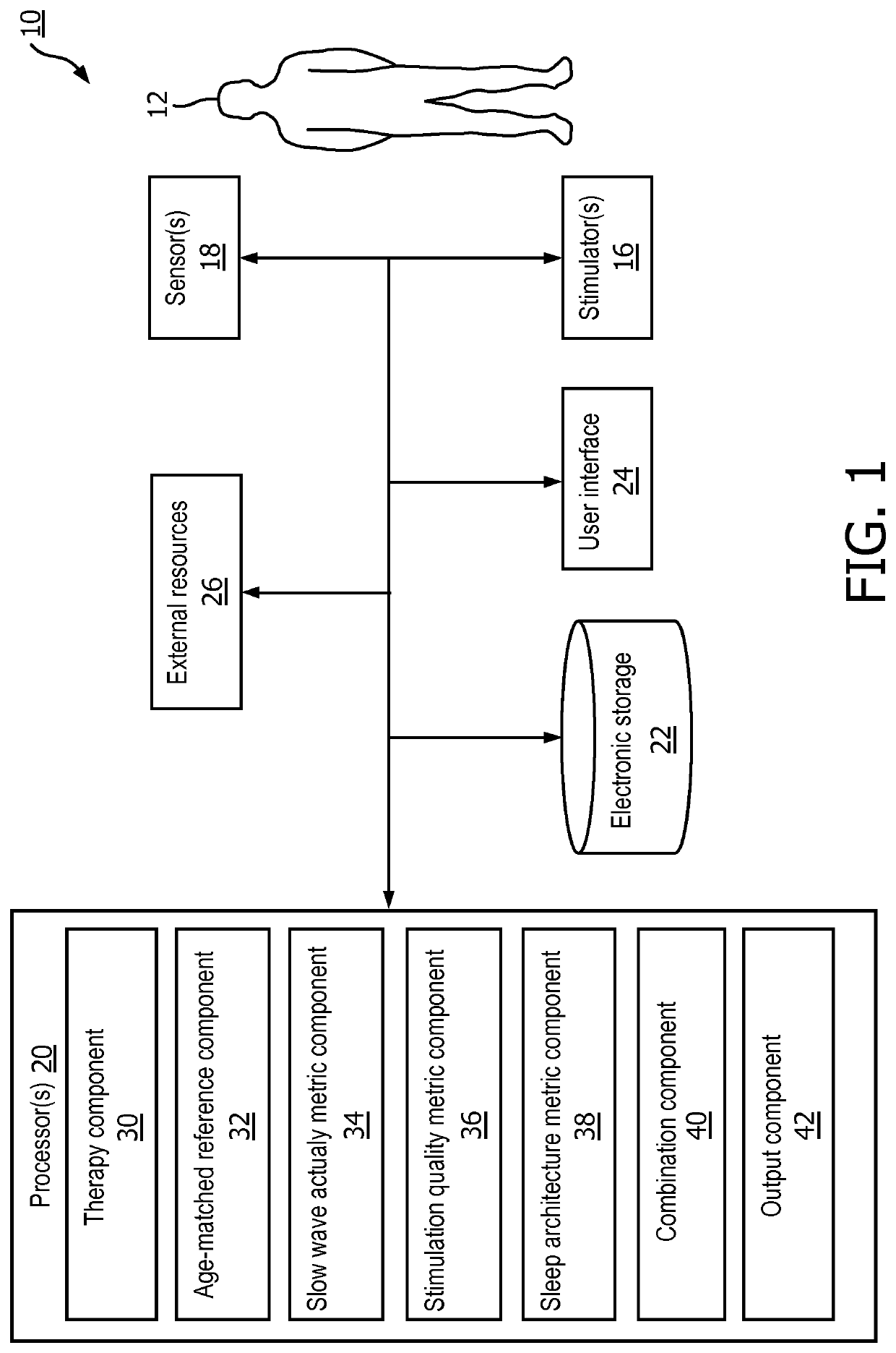
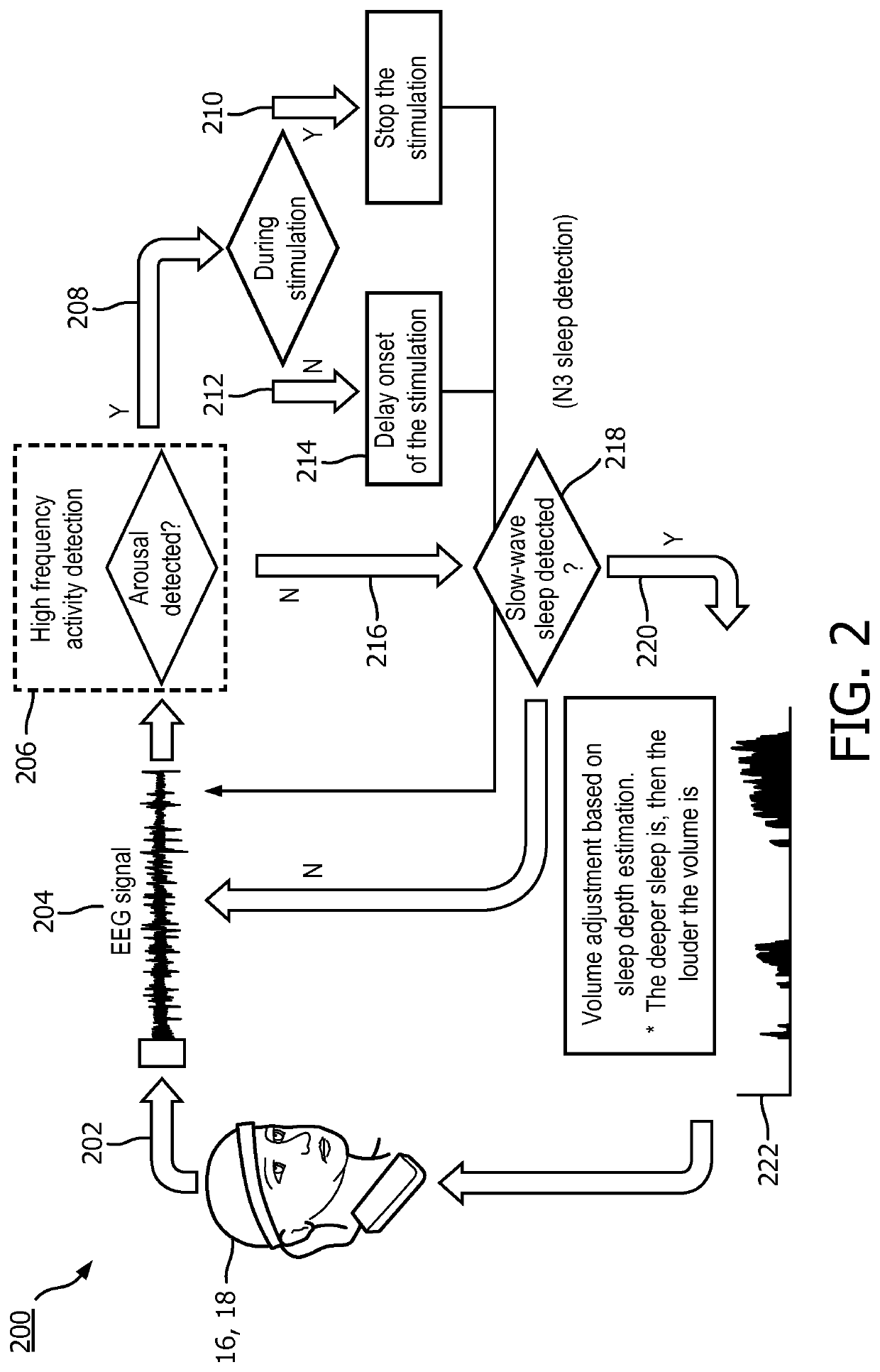
The present patent describes a system and method for providing an indicator to a subject during a sleep session that represents the effects of stimulation provided to the subject during the session. This system includes stimulators, sensors, hardware processors, and software components that determine the indicators based on the generated output signals conveying information related to brain activity and the stimulation provided to the subject. The indicators include a slow wave activity metric, which is a measure of the amount of slow wave activity during the session, a stimulation quality metric, which is a measure of how well the stimulation enhances slow wave activity, and a sleep architecture metric, which is a measure of the quality of the sleep session. These indicators are combined to determine the overall indicator, which is then displayed to the subject. This system and method can help improve the effectiveness and quality of stimulation during sleep sessions.

Problems solved by technology

Typically, systems for monitoring sleep do not automatically generate an output that informs a user of the benefits of stimulation provided during a sleep session.

Method used


Image

  • System and method for outputting an indicator representative of the effects of stimulation provided to a subject during sleep
  • System and method for outputting an indicator representative of the effects of stimulation provided to a subject during sleep
  • System and method for outputting an indicator representative of the effects of stimulation provided to a subject during sleep

Examples


Embodiment Construction

[0026]As used herein, the singular form of “a”, “an”, and “the” include plural references unless the context clearly dictates otherwise. As used herein, the statement that two or more parts or components are “coupled” shall mean that the parts are joined or operate together either directly or indirectly, i.e., through one or more intermediate parts or components, so long as a link occurs. As used herein, “directly coupled” means that two elements are directly in contact with each other. As used herein, “fixedly coupled” or “fixed” means that two components are coupled so as to move as one while maintaining a constant orientation relative to each other.

[0027]As used herein, the word “unitary” means a component is created as a single piece or unit. That is, a component that includes pieces that are created separately and then coupled together as a unit is not a “unitary” component or body. As employed herein, the statement that two or more parts or components “engage” one another shal...


PUM


Abstract

The present disclosure pertains to a system configured to output an indicator representative of effects of stimulation provided to a subject during a sleep session. The indicator is determined based on a combination of the effect of stimulation on sleep restoration, stimulation quality, sleep architecture factors, and / or other information. The indicator is determined using age matched reference information on deep sleep duration and EEG slow wave activity. The contribution to the indicator associated with sleep architecture factors is determined based on age matched reference information including sleep onset latency, wake after sleep onset, total sleep time, micro-arousal count, sleep stage(s) prior to awakening, and / or other information.

Description

CROSS-REFERENCE TO PRIOR APPLICATIONS[0001]This application is the U.S. National Phase application under 35 U.S.C. § 371 of International Application Serial No. PCT / EP2017 / 084078, filed on 21 Dec. 2017, which claims the benefit of U.S. application Ser. No. 62 / 437,973, filed on 22 Dec. 2016. These applications are hereby incorporated by reference herein.BACKGROUND1. Field[0002]The present disclosure pertains to a system and method for outputting an indicator representative of effects of stimulation provided to a subject during a sleep session.2. Description of the Related Art[0003]Systems for monitoring sleep are known. The restorative value of sleep can be increased by delivering appropriately timed auditory stimulation during deep sleep to enhance sleep slow waves. Typically, systems for monitoring sleep do not automatically generate an output that informs a user of the benefits of stimulation provided during a sleep session. The present disclosure overcomes deficiencies in prior a...

Claims


Application Information

Patent Timeline
Patent Type & Authority Patents(United States)
IPC IPC(8): A61B5/00A61B5/048A61M21/02A61B5/374A61M21/00
CPCA61B5/4815A61B5/374A61B5/4812A61B5/4848A61M21/02A61B5/4836A61M2021/0027A61M2230/10A61M2230/005
Inventor GARCIA MOLINA, GARY NELSONTSONEVA, TSVETOMIRA KIROVAPFUNDTNER, STEFANVISSAPRAGADA VENKATA SATYA, SURYA SUBRAHMANYA SREERAMMAHADEVAN, ANANDIKOSOBUD, DIANE
Owner KONINKLJIJKE PHILIPS NV
Learn More