
Cup plug insertion tool

a technology for insertion tools and cup plugs, which is applied in the field of tools for insertion of cup plugs, can solve the problems of increasing the likelihood of leaking joints, high incidence of sporadic failures in current cup plug press operations, and high incidence of failures, so as to reduce the outer diameter of the first section

Active Publication Date: 2022-02-22
GM GLOBAL TECH OPERATIONS LLC
View PDF4 Cites 0 Cited by
  • Summary
  • Abstract
  • Description
  • Claims
  • Application Information

AI Technical Summary

Benefits of technology

The patent describes a tool that helps insert a cup plug into a die. However, existing tools have problems with centering and can create a gouging effect or damage the plug. The tool described in the patent tries to address these issues by using flexible segments that can move inward to reduce the size of the collet and make it easier to insert the cup plug. This helps improve the manufacturing process and make it easier to produce quality products.

Problems solved by technology

Current cup plug press operations suffer a high incidence of sporadic failures during post operation leak test.
The failures are frequently associated and appear physically correlated to excessive press force upon insertion.
This droop creates a gouging effect near the bottom of the bore during press, increasing the likelihood of a leaking joint.
An interference fit between the outer diameter of the tool and the inner diameter of the cup plug centers the cup plug effectively, but occasionally results in the cup plug deforming and tightly grabbling the tool.
If there is too much friction between the outer diameter of the tool and the inner diameter of the cup plug, the cup plug may remain on the tool and get pulled out upon tool retraction.

Method used


Image

  • Cup plug insertion tool
  • Cup plug insertion tool
  • Cup plug insertion tool

Examples


Embodiment Construction

[0034]The following description is merely exemplary in nature and is not intended to limit the present disclosure, application, or uses.

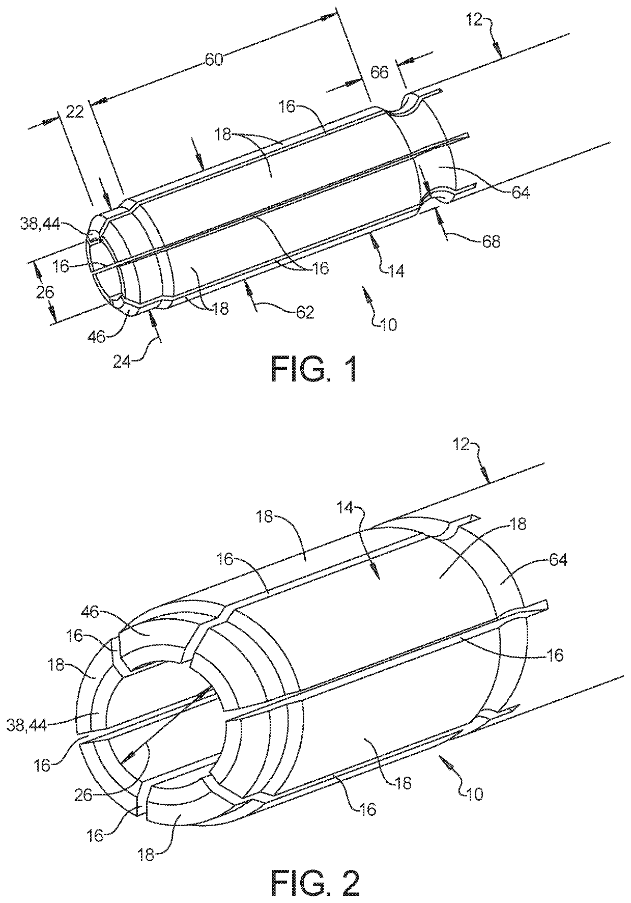
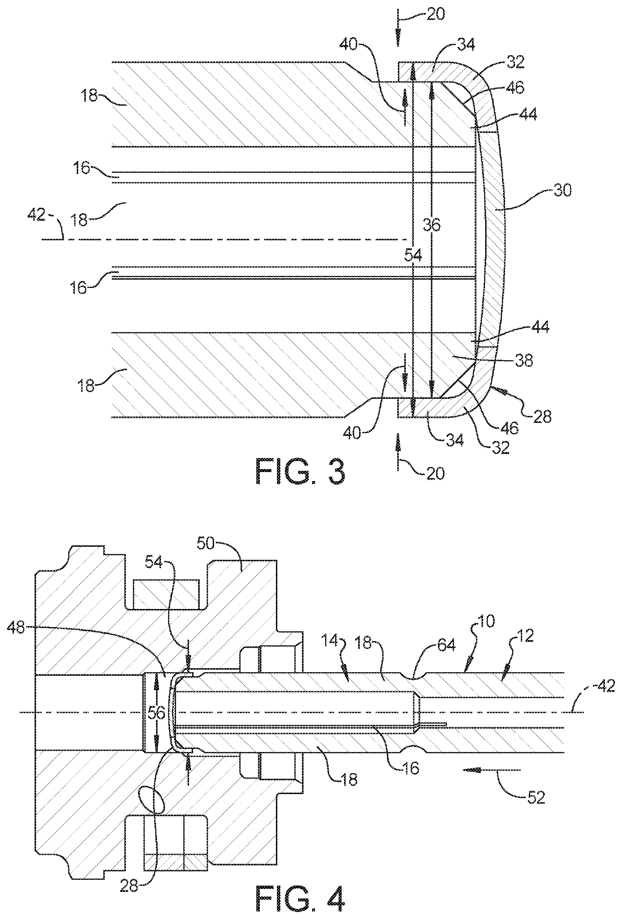
[0035]Referring to FIG. 1 and FIG. 2, a cup plug insertion tool 10 in accordance with the present disclosure includes a cylindrical base 12 and a cylindrical collet 14 extending from the base 12. The collet 14 includes at least two longitudinal slots 16 that divide the collet 14 into at least two flexible segments 18. In the exemplary embodiment shown in FIG. 1 and FIG. 2, the collet 14 includes six longitudinal slots 16 spaced equidistantly around the collet 14 that divide the collet 14 into six identical flexible segments 18.

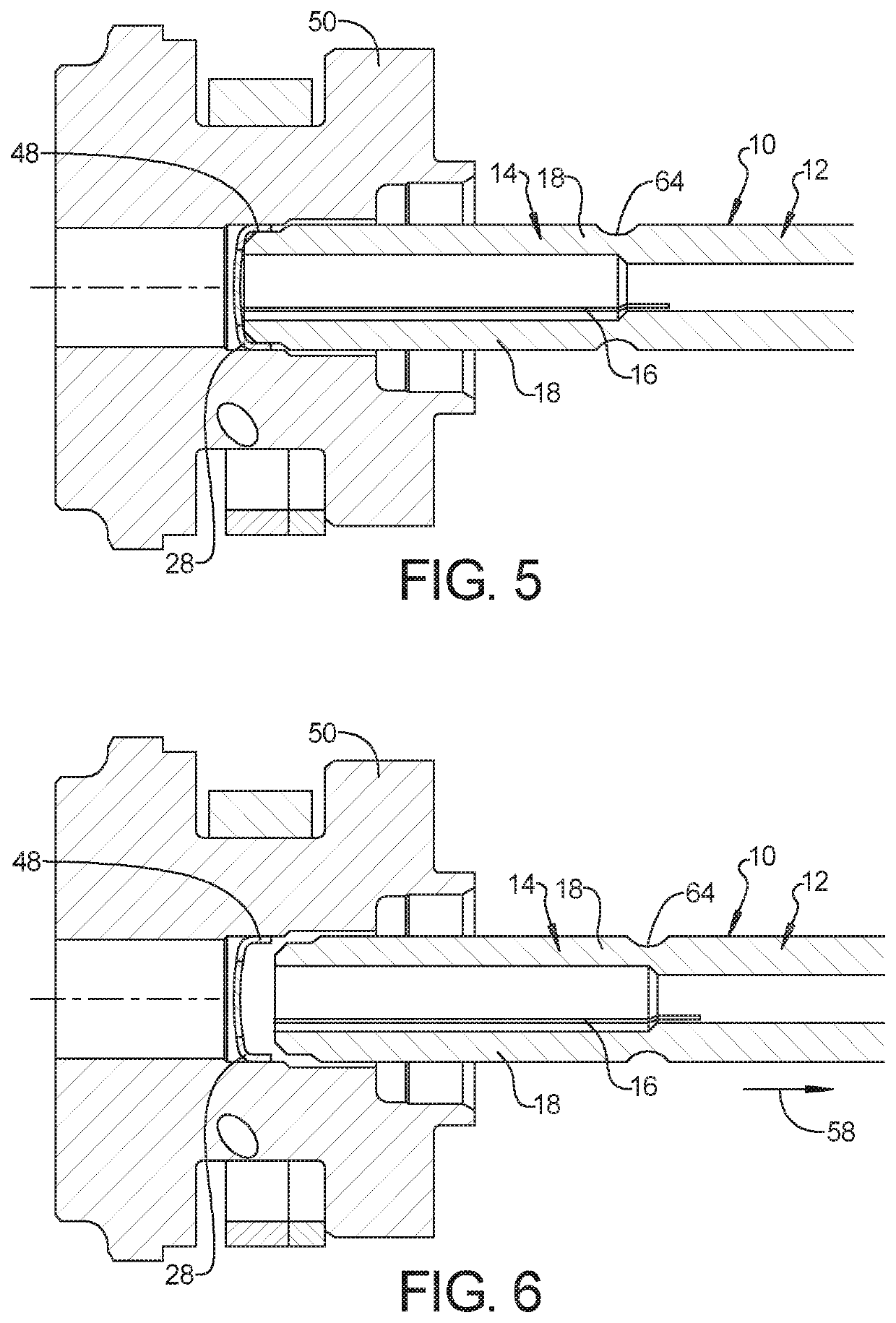
[0036]The flexible segments 18 are adapted to flex radially inward under force, as indicated by arrows 20. The collet 14 includes a first section 22 that defines a circumferential outer diameter 24 and a circumferential inner diameter 26. Referring to FIG. 3, the cup plug insertion tool 10 is adapted to insert a cup plug 28 ha...


PUM


Abstract

A cup plug insertion tool comprises a cylindrical base and a cylindrical collet extending from the base and including at least two longitudinal slots that divide the collet into at least two flexible segments adapted to flex radially inward under force, an annular groove formed adjacent the base, the annular groove adapted to allow the flexible segments to flex radially inward, further wherein, the force necessary to flex the flexible segments radially inward is tunable based on a width and depth of the annular groove, a first section defining a circumferential outer diameter and a circumferential inner diameter, a second section defining a circumferential outer diameter that is larger than the circumferential outer diameter of the first section, a tip positioned at the distal end of the collet, and a chamfer formed between the outer diameter of the first section and the tip.

Description

INTRODUCTION[0001]The present disclosure relates to a tool for inserting cup plugs in automotive applications. Current cup plug press operations suffer a high incidence of sporadic failures during post operation leak test. The failures are frequently associated and appear physically correlated to excessive press force upon insertion.[0002]One known tool features significant relief between the outer diameter of the tool and the inner diameter of the cup plug. In this arrangement, the centering is completely dependent upon the presentation of the cup plug to the tool and upon the vacuum and friction with which the cup plug is held against the tool. Significant droop, where the plug moves or falls with gravity downward to contact the top of the tool outer diameter may occur. This droop creates a gouging effect near the bottom of the bore during press, increasing the likelihood of a leaking joint. Another known tool utilizes a much tighter tolerance between the outer diameter of the too...

Claims


Application Information

Patent Timeline
Patent Type & Authority Patents(United States)
IPC IPC(8): B25B27/02
CPCB25B27/02B25B27/0035B25B27/0028
Inventor DEGRACE, GARROLD A.GONZALEZ GILLIS, GABRIELHILBER, PATRICK M.
Owner GM GLOBAL TECH OPERATIONS LLC
Learn More