Air conditioning register

a technology of air conditioner and register, which is applied in the direction of vehicle components, vehicle heating/cooling devices, transportation and packaging, etc., can solve the problems of user discomfort, inability to regulate the displacement of the fork, and abnormal noise generated by the contact between the two, so as to prevent the transmission shaft and prevent abnormal nois

Active Publication Date: 2022-02-22
TOYODA GOSEI CO LTD
View PDF5 Cites 0 Cited by
  • Summary
  • Abstract
  • Description
  • Claims
  • Application Information

AI Technical Summary

Benefits of technology

[0006]An object of the present invention is to prevent the generation of abnormal noise when the fork contacts the stopper.
[0008]When the inclination angle of the inclined surface with respect to the center axis of the transmission shaft is less than “9°”, there is a possibility that the displacement of the fork cannot be regulated by the stopper because the thickness of the stopper is not thick enough with respect to a distance between the pair of transmission pieces. In this point, according to the above-described configuration, the inclination angle is the angle equal to or greater than “9°”. Therefore, the displacement of the fork can be regulated by causing the transmission piece to contact the stopper by the rotation of the operation knob. That is, it is possible to regulate the rotation of the operation knob and the downstream side fin connected to the fork.
[0010]In the above-described configuration, the inclination angle is the angle equal to or greater than “9°” and equal to or less than “14°”. Therefore, by causing the transmission piece to contact the stopper, further rotation of the operation knob and the downstream side fin is regulated, and the generation of abnormal noise caused by the contact between the transmission piece and the stopper is prevented.
[0015]In this point, according to the above-described configuration, the center axis of the stopper is inclined with respect to the center axis of the transmission shaft so that the inclination angle of the inclined surface at the portion on the upstream side in the flow direction of the stopper is greater than the inclination angle of the inclined surface at the portion on the downstream side in the flow direction of the stopper. Accordingly, the inclined surface at the portion on the upstream side in the flow direction can be disposed closer to the center side in the extending direction of the transmission shaft than the inclined surface at the portion on the downstream side in the flow direction. As a result, when the pair of transmission pieces are caused to approach the stopper by the rotation of the operation knob, the transmission piece can be caused to contact the stopper before the transmission shaft is detached to the outside from the space between the tips of the pair of transmission pieces. That is, it is possible to prevent the transmission shaft from being detached from the space between the pair of transmission pieces.
[0016]According to the above-described air conditioning register, it is possible to prevent generation of an abnormal noise when a fork contacts a stopper.

Problems solved by technology

When a transmission piece of a fork contacts a stopper by displacement of the fork caused by an operation of an operation knob by a user an abnormal noise is generated by the contact therebetween.
When the abnormal noise is large at this time, the user may feel uncomfortable.
When the inclination angle of the inclined surface with respect to the center axis of the transmission shaft is less than “9°”, there is a possibility that the displacement of the fork cannot be regulated by the stopper because the thickness of the stopper is not thick enough with respect to a distance between the pair of transmission pieces.
On the other hand, as the inclination angle is greater, an abnormal noise generated when the transmission piece contacts the stopper is easy to become large.

Method used


Image

  • Air conditioning register
  • Air conditioning register
  • Air conditioning register

Examples


first embodiment

[0029]Hereinafter, a first embodiment of an air conditioning register will be described with reference to FIGS. 1 to 7.

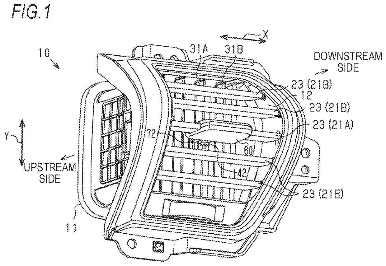
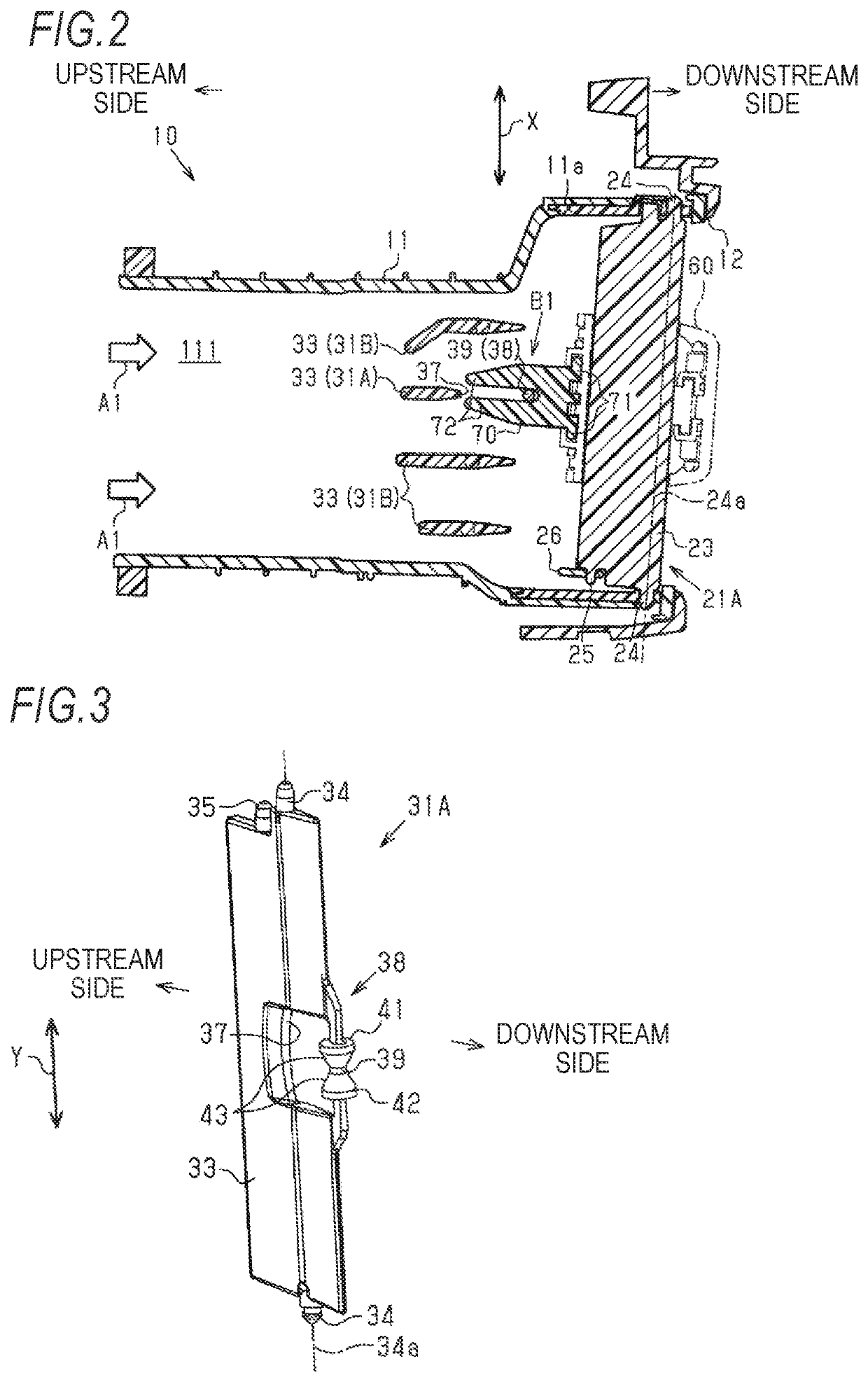
[0030]FIG. 1 illustrates an air conditioning register 10 provided in an on-vehicle air conditioner. For example, the air conditioning register 10 is incorporated in both side parts or a center part in a vehicle width direction X of an instrument panel of a vehicle. As illustrated in FIGS. 1 and 2, the air conditioning register 10 includes a retainer 11 having a cylindrical shape. A ventilation path 111 through which air-conditioning air sent from the air conditioner flows is formed inside the retainer 11. A direction in which the air-conditioning air flows in the ventilation path 111 is referred to as a “flow direction A1”. In the flow direction A1, aside close to the air conditioner is defined as an upstream side, and a side farther from the air conditioner is defined as a downstream side. Then, the air-conditioning air flowing through the ventilation path 111 is b...

second embodiment

[0053]Next, a second embodiment of the air conditioning register will be described with reference to FIGS. 8 to 12. In the following description, portions that are different from those of the first embodiment will be mainly described, and the same or corresponding member configurations as those of the first embodiment will be denoted by the same reference signs, and the description thereof will be omitted.

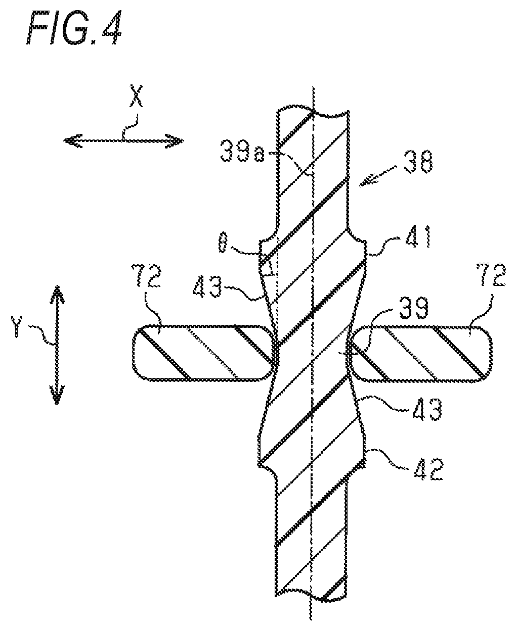
[0054]FIG. 8 illustrates a transmission shaft 38A provided in the upstream side fin 31A in the air conditioning register 10 of the embodiment. The transmission shaft 38A includes a main body shaft part 39 and a pair of stoppers 41A and 42. Of the pair of stoppers 41A and 42, a shape of the stopper 42 on the lower side in the drawing is the same as that described in the first embodiment. That is, the center axis of the stopper 42 is located on the extension line of the center axis 39a of the main body shaft part 39. On the other hand, a shape of the stopper 41A on the upper side in ...


PUM


Abstract

An air conditioning register includes: a downstream side fin; an upstream side fin; an operation knob; and a fork including a pair of transmission pieces, and connected to the operation knob. A transmission shaft is provided in the upstream side fin, and is interposed between the pair of transmission pieces. The transmission shaft is provided with a stopper that regulates further displacement of the fork. A surface of the stopper is an inclined surface that is inclined with respect to a center axis of the transmission shaft so as to be located outside in a radial direction centering on the center axis of the transmission shaft as approaching an end of the transmission shaft. An inclination angle of the inclined surface with respect to the center axis of the transmission shaft is an angle equal to or greater than 9° and equal to or less than 14°.

Description

CROSS-REFERENCE TO RELATED APPLICATION(S)[0001]This application is based upon and claims the benefit of priority from prior Japanese patent application No. 2019-130917 filed on Jul. 16, 2019, the entire contents of which are incorporated herein by reference.BACKGROUND1. Field of the Invention[0002]The present invention relates to an air conditioning register in which a fin is provided in a ventilation path for air-conditioning air.2. Description of the Related Art[0003]JP-A-2015-218913 describes an example of an air conditioning register. This air conditioning register includes a downstream side fin and an upstream side fin disposed upstream of the downstream side fin in a flow direction of air-conditioning air. An extending direction of the downstream side fin is almost orthogonal to an extending direction of the upstream side fin. A transmission shaft is provided in the upstream side fin.[0004]The downstream side fin supports an operation knob rotating together with the downstream...

Claims


Application Information

Patent Timeline
Patent Type & Authority Patents(United States)
IPC IPC(8): B60H1/34
CPCB60H1/3421B60H2001/3471
Inventor ITO, KENICHITANIKAWA, TATSUYAMITSUI, YASUYUKI
Owner TOYODA GOSEI CO LTD
Why Eureka
Try Eureka