Cutting apparatus

a cutting machine and cutting shaft technology, applied in mechanical equipment, manufacturing tools, gearing, etc., can solve the problems of increasing cost, affecting the quality of cutting equipment, so as to reduce the size, weight, or cost

Active Publication Date: 2022-03-08
DISCO CORP
View PDF11 Cites 0 Cited by
  • Summary
  • Abstract
  • Description
  • Claims
  • Application Information

AI Technical Summary

Benefits of technology

[0006]It is therefore an object of the present invention to provide a cutting apparatus having a blade changing apparatus which can be reduced in size, weight, or cost.
[0009]The cutting apparatus of the present invention includes the blade changing apparatus for changing the cutting blade. The blade changing apparatus includes the motor, the rotating shaft, the first nut rotating portion fixed to one end of the rotating shaft, the second nut rotating portion fixed to the other end of the rotating shaft, and the power transmitting unit for transmitting the power of the motor to the rotating shaft. The blade changing apparatus can transmit the power of the motor through the power transmitting unit and the rotating shaft to the first nut rotating portion and the second nut rotating portion. That is, the two nut rotating portions can be driven by a single motor. Accordingly, it is unnecessary to provide individual motors for the first nut rotating portion and the second nut rotating portion, so that the blade changing apparatus can be reduced in size, weight, or cost.

Problems solved by technology

However, each motor for rotating each nut rotating portion has a considerable size and weight.
Further, in configuring and operating such a blade changing apparatus, a plurality of motors must be prepared and maintenance therefore is required, causing an increase in cost.

Method used


Image

  • Cutting apparatus
  • Cutting apparatus
  • Cutting apparatus

Examples


Embodiment Construction

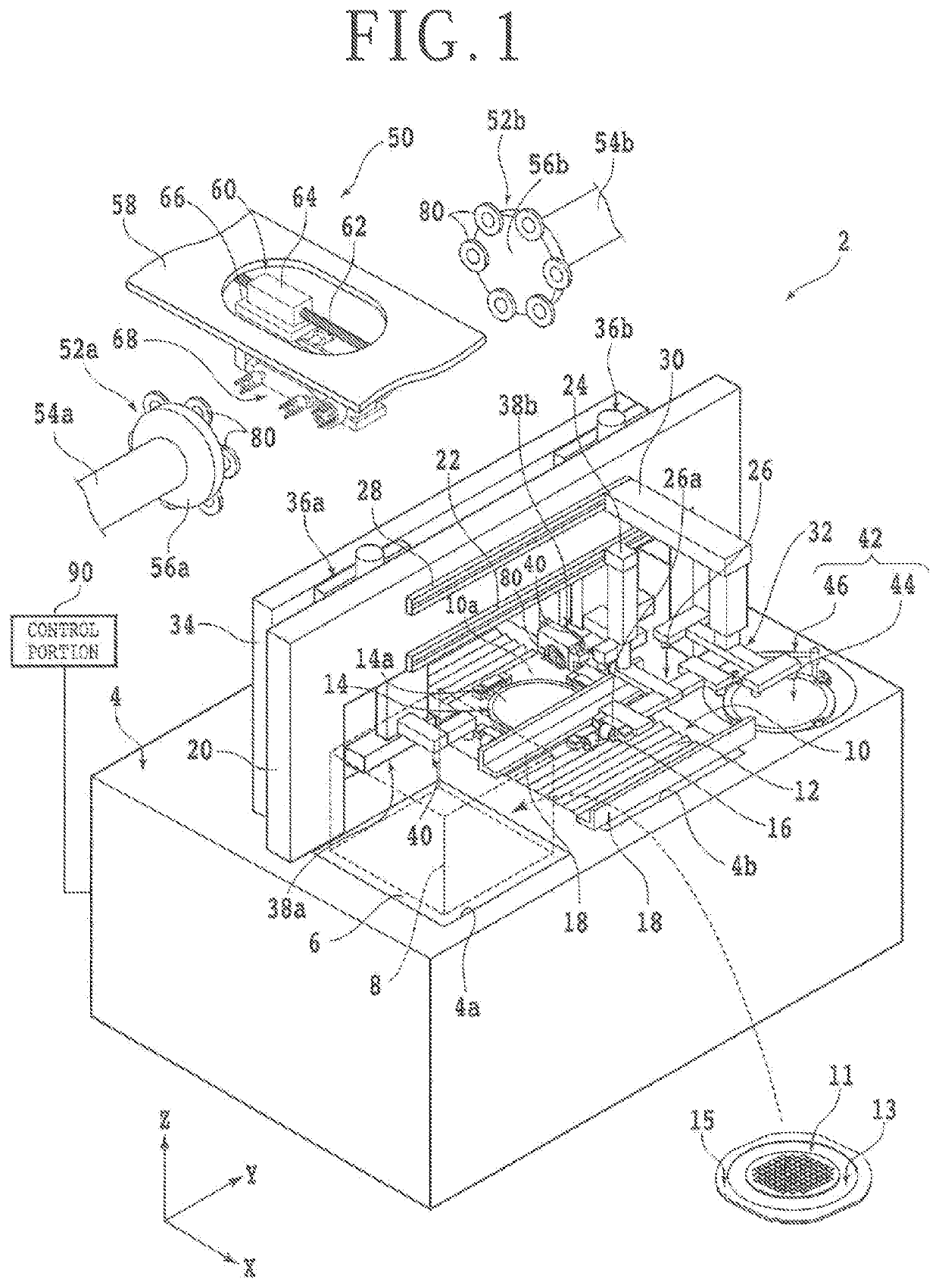
[0016]A preferred embodiment of the present invention will now be described with reference to the attached drawings. There will first be described a cutting apparatus 2 according to this preferred embodiment with reference to FIG. 1. FIG. 1 is a perspective view of the cutting apparatus 2.

[0017]As depicted in FIG. 1, the cutting apparatus 2 includes a base housing 4 for supporting various components of the cutting apparatus 2. A rectangular opening 4a is formed on the upper surface of the base housing 4 at a left front corner portion thereof. A cassette support table 6 is provided in the rectangular opening 4a so as to be vertically movable by an elevating mechanism (not depicted). A cassette 8 is adapted to be mounted on the upper surface of the cassette support table 6. The cassette 8 is capable of storing a plurality of workpieces 11. In FIG. 1, the outline of the cassette 8 is depicted by a broken line.

[0018]Each workpiece 11 is a disk-shaped wafer formed of a semiconductor such...


PUM

PropertyMeasurementUnit
poweraaaaaaaaaa
axis of rotationaaaaaaaaaa
rotational speedaaaaaaaaaa

Abstract

A cutting apparatus includes a blade changing apparatus for changing a cutting blade mounted on a spindle of a first cutting unit and changing a cutting blade mounted on a spindle of a second cutting unit. The blade changing apparatus includes a nut mounting and demounting unit for mounting and demounting a nut in each of the first and second cutting units and a blade mounting and demounting unit for mounting and demounting the cutting blade in each of the first and second cutting units. The nut mounting and demounting unit includes a rotating shaft, a first nut rotating portion fixed to one end of the rotating shaft, a second nut rotating portion fixed to the other end of the rotating shaft, a motor, and a power transmitting unit connected to the motor and the rotating shaft.

Description

BACKGROUND OF THE INVENTIONField of the Invention[0001]The present invention relates to a cutting apparatus for cutting a workpiece.Description of the Related Art[0002]In a device chip fabrication process, a wafer having a plurality of devices on the front side is used. That is, the front side of the wafer is partitioned by a plurality of crossing division lines (streets) to thereby define a plurality of separate regions where the plural devices such as integrated circuits (ICs) and large scale integration (LSI) circuits are respectively formed. By dividing the wafer along the division lines, a plurality of device chips respectively including the plural devices can be obtained.[0003]For example, a cutting apparatus is used to divide the wafer. The cutting apparatus includes a chuck table for holding the wafer and a cutting unit for cutting the wafer held on the chuck table. The cutting unit includes a spindle (rotating shaft) and an annular cutting blade mounted on the spindle for c...

Claims


Application Information

Patent Timeline
Patent Type & Authority Patents(United States)
IPC IPC(8): B26D7/26B26D1/15B26D1/00F16H1/14
CPCB26D7/2621B26D1/0006B26D1/15B26D2001/0046F16H1/145B28D5/02B28D5/0058B28D5/0094B28D5/0011B28D5/0029B28D5/0052F16H1/203B28D1/22H01L21/67092B23Q3/15722B28D5/0082Y10T483/174
Inventor SU, ZHIBOTERADA, KAZUKI
Owner DISCO CORP
Why Eureka
Try Eureka