Display device and terminal

a display device and terminal technology, applied in the field of display technologies, can solve the problems of excessive pins, inability to meet the requirements of narrow frames, and large so as to reduce the number of electrode lines, the number of pins, and the width of flexible circuit boards.

Active Publication Date: 2022-03-15
SHENZHEN CHINA STAR OPTOELECTRONICS SEMICON DISPLAY TECH CO LTD
View PDF12 Cites 0 Cited by
  • Summary
  • Abstract
  • Description
  • Claims
  • Application Information

AI Technical Summary

Benefits of technology

[0033]The beneficial effects of the invention are: The present invention provides a display device and a terminal. The display device comprises a display panel and a touch layer formed on one side of the display panel. The touch layer comprises a plurality of first touch electrodes and a plurality of second touch electrodes disposed in a same layer and not in contact with each other, each of the first touch electrodes is connected to a first electrode line, and each of the second touch electrodes is connected to a second electrode line. The first touch electrodes and the second touch electrodes are alternately arranged in a first direction, and the second touch electrodes comprises a plurality of touch units arranged in a second direction and connected with each other. The second direction is perpendicular to the first direction, and surface areas of the plurality of touch units in the same second touch electrode are not equal. By disposing the second touch electrodes as a plurality of touch units that are connected to each other and have different surface areas, and making the touch units corresponding to the same first touch electrode, when fingers touch different positions on the second touch electrode, the corresponding capacitance values change differently. Therefore, the capacitance change values of a plurality of points on the second touch electrode can be measured through one second electrode line, thereby greatly reducing a number of electrode lines. The number of pins required for subsequent binding to a flexible circuit board is also greatly reduced, thereby reducing a width of the flexible circuit board and achieving narrow frames.
are: The present invention provides a display device and a terminal. The display device comprises a display panel and a touch layer formed on one side of the display panel. The touch layer comprises a plurality of first touch electrodes and a plurality of second touch electrodes disposed in a same layer and not in contact with each other, each of the first touch electrodes is connected to a first electrode line, and each of the second touch electrodes is connected to a second electrode line. The first touch electrodes and the second touch electrodes are alternately arranged in a first direction, and the second touch electrodes comprises a plurality of touch units arranged in a second direction and connected with each other. The second direction is perpendicular to the first direction, and surface areas of the plurality of touch units in the same second touch electrode are not equal. By disposing the second touch electrodes as a plurality of touch units that are connected to each other and have different surface areas, and making the touch units corresponding to the same first touch electrode, when fingers touch different positions on the second touch electrode, the corresponding capacitance values change differently. Therefore, the capacitance change values of a plurality of points on the second touch electrode can be measured through one second electrode line, thereby greatly reducing a number of electrode lines. The number of pins required for subsequent binding to a flexible circuit board is also greatly reduced, thereby reducing a width of the flexible circuit board and achieving narrow frames.

Problems solved by technology

Since an input terminal corresponds to multiple detection terminals, and each the input terminals and each the detection terminals need to be connected to an electrode line and a pin, which eventually causes too many pins to be needed, and the flexible circuit board has a large width and cannot meet requirements of narrow frames.
Therefore, current display devices have technical problems that the electrode lines of touch electrodes are excessive and need to be improved.

Method used


Image

  • Display device and terminal
  • Display device and terminal
  • Display device and terminal

Examples


Embodiment Construction

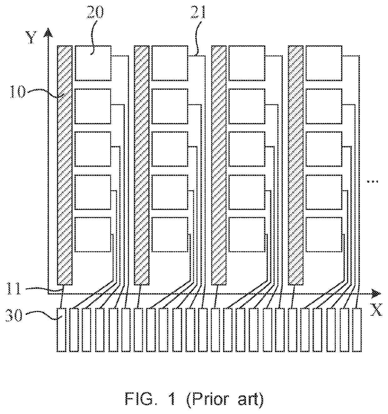
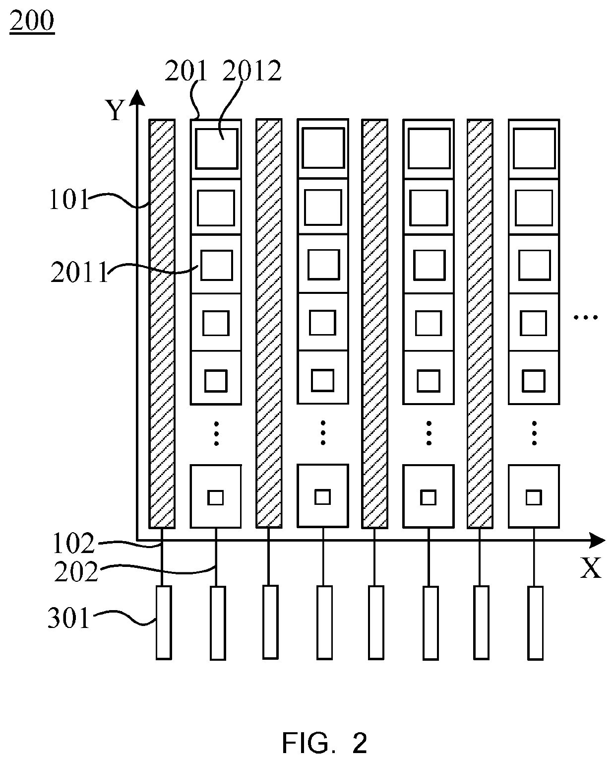
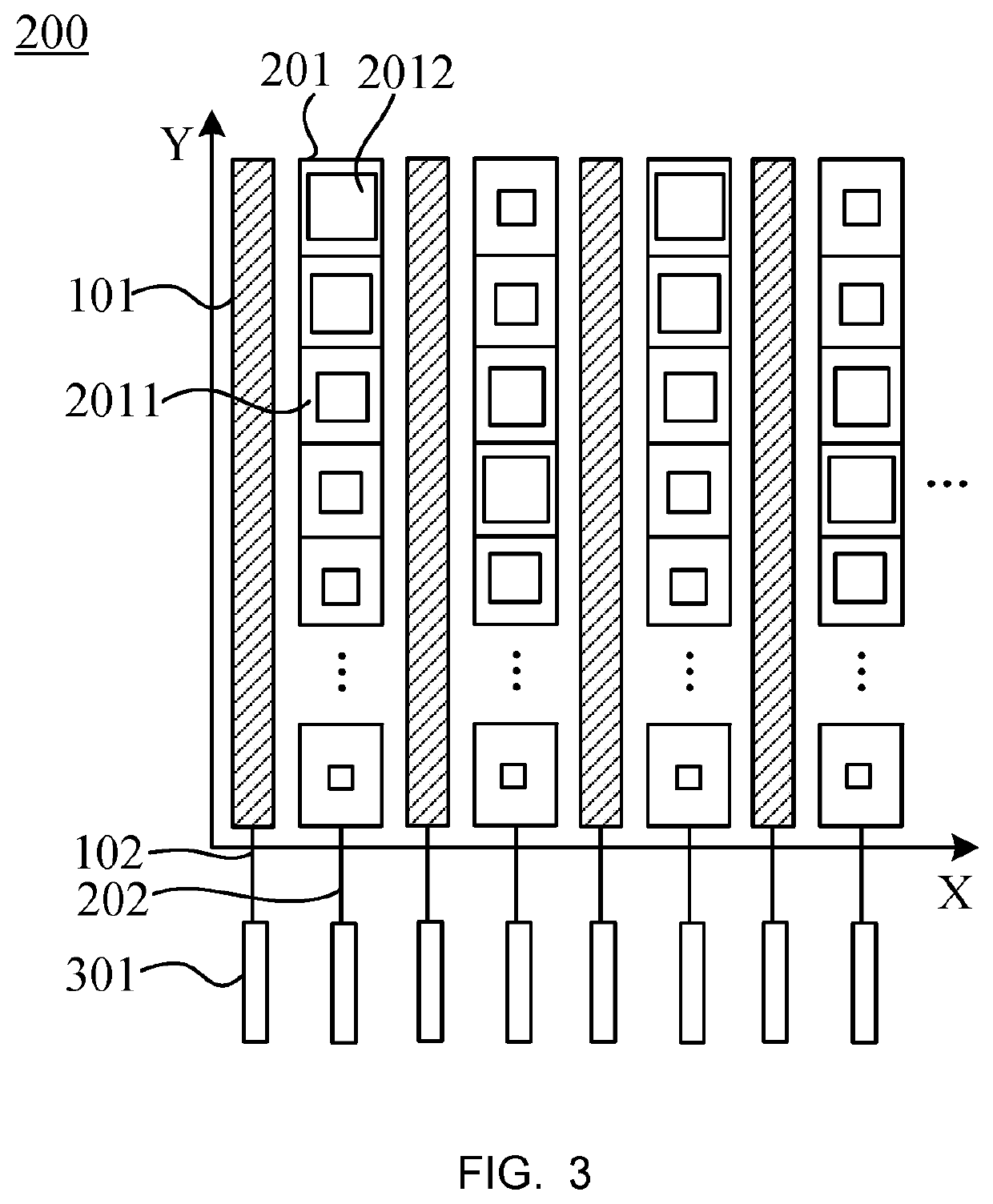
[0039]The following description of the various embodiments is provided with reference to the accompanying drawings. Directional terms, such as upper, lower, front, back, left, right, inner, outer, and lateral side, mentioned in the present invention are only for reference. Therefore, the directional terms are used for describing and understanding rather than limiting the present invention. In the figures, units having similar structures are used for the same reference numbers.

[0040]The present invention provides a display device and a terminal to alleviate a technical problem that electrode lines of touch electrodes in current display devices are excessive.

[0041]As shown in FIG. 2, the present invention provides a display device and a terminal. The display device comprises a display panel and a touch layer 200 formed on one side of the display panel. The touch layer comprises a plurality of first touch electrodes 101 and a plurality of second touch electrodes 102 disposed in a same ...


PUM

PropertyMeasurementUnit
surface areasaaaaaaaaaa
surface shapeaaaaaaaaaa
mutual capacitanceaaaaaaaaaa

Abstract

The present invention provides a display device and a terminal. The display device includes a display panel and a touch layer. The touch layer includes a plurality of first touch electrodes and a plurality of second touch electrodes disposed in a same layer and not in contact with each other. The first touch electrodes and the second touch electrodes are alternately arranged in a first direction. The second touch electrodes include a plurality of touch units arranged in a second direction and connected with each other. Surface areas of the plurality of touch units in the same second touch electrode are not equal. The invention reduces a width of a flexible circuit board.

Description

FIELD OF INVENTION[0001]The present application relates to the field of display technologies, and in particular, to a display device and a terminal.BACKGROUND OF INVENTION[0002]In current touch panel using a single-layer mutual capacitance structure, drive electrodes and sensing electrodes are close to each other to form lateral capacitances. The driving electrodes are used as input terminals to input sine wave signals, and the sensing electrodes are used as detection terminals. When fingers touch a surface of the touch panel, coordinates of touch positions are determined according to detected changes of input signals.[0003]Both the input terminals and the detection terminals need to be connected to pins on flexible circuit boards through electrode lines. Since an input terminal corresponds to multiple detection terminals, and each the input terminals and each the detection terminals need to be connected to an electrode line and a pin, which eventually causes too many pins to be nee...

Claims


Application Information

Patent Timeline
Patent Type & Authority Patents(United States)
IPC IPC(8): G06F3/044G06F3/041
CPCG06F3/0443G06F3/0446G06F3/0448G06F3/04164H04L9/0894H04L9/0891G06F3/0412G06F3/0416G06F3/044
Inventor ZHENG, JIEXINLIU, QIKUN
Owner SHENZHEN CHINA STAR OPTOELECTRONICS SEMICON DISPLAY TECH CO LTD
Why Eureka
Try Eureka