Linearly actuated vehicle providing increased force actuation

a linear actuator and vehicle technology, applied in the direction of bicycles, bicycle components, rider propulsion, etc., can solve the problems of inefficiency too low, the wheel base of the resulting bicycle is substantially longer than that of a conventional bicycle, and the crank transmission of the '684 patent provides only about 24% or less muscle efficiency, so as to achieve greater speed and distance of travel, increase the speed of the vehicle, and reduce the effect of power transfer

Active Publication Date: 2022-03-29
CYCLAZOOM LLC
View PDF65 Cites 0 Cited by
  • Summary
  • Abstract
  • Description
  • Claims
  • Application Information

AI Technical Summary

Benefits of technology

[0018]The human-powered vehicle of the present invention has a very efficient power transfer to the wheels, thereby increasing the speed of the vehicle as compared to typical recumbent bicycles and tricycles, permitting a greater speed and distance of travel, and allowing to carry additional weight, such as, for example, extra passengers. Typical crank-operated human-powered vehicles such as bicycles and tricycles are capable of only 24% muscle efficiency as compared to the novel linear drive and double-overrunning clutch transmission utilized in the present invention, which use approximately 90% or higher muscle efficiency. The increased efficiency, relatively lighter weight, comfort and ease of steering of the human-powered vehicle described herein, make it as an alternative to fuel-consuming vehicles for local travel and transport of lighter weight loads.
[0019]A particular feature of the recumbent position and frame of the vehicle described herein is a riding position that, compared with the upright seated position, affords more efficient and comfortable propulsion, where muscle stress may be more readily alternated among muscles groups of both the front and back of the body. The recumbent position of the seat in the present invention offers additional medical benefits that are well-known and described in the art of recumbent cycling, such as, for example, decreased pressure on the groin area.
[0020]Due to the relatively short wheel base of embodiments of a bicycle in accordance with the present invention and its unique linear drive transmission, the human-powered vehicle of the present invention is generally capable of attaining speeds substantially higher than those of conventional crankshaft-operated recumbent bicycles and tricycles. The combination of the design with a short wheel base and the linear drive mechanism described herein also permits the user of the vehicle to propel heavier loads, such as additional passengers, groceries, and other weight.

Problems solved by technology

In addition, as explained below, the crank transmission of the '684 patent provides only about 24% or less muscle efficiency.
Such inefficiency is too low, especially for a larger, heavier vehicle described in the '684 patent.
First, due to the length of the pedal sliders described in the '922 patent, the wheel base of the resulting bicycle is substantially longer than that of a conventional bicycle.
Thus, similar to the '684 patent, the bicycle of the '922 patent is both long and heavy, and suffers from the same disadvantages as the '684 patent bicycle.
Moreover, the design described in the '922 patent has a potential problem with stability and requires retractable stabilizer wheels, which make this design dangerous and impractical for most riders.
Indeed, the aforementioned disadvantages are typical of most recumbent bicycles known in the art.
Second, the recumbent bicycle of the '922 patent does not allow for independent pedal motion wherein the rider chooses simultaneous or alternating pedal motion, which may be powered by a rider having only one leg.
Finally, the '922 patent lacks in power efficiency provided with the use of the novel linear drive mechanism connected by a flexible power link to a double overrunning clutch transmission with returning springs.
Additional prior art references accumulate many of the problems described above.

Method used


Image

  • Linearly actuated vehicle providing increased force actuation
  • Linearly actuated vehicle providing increased force actuation
  • Linearly actuated vehicle providing increased force actuation

Examples


Embodiment Construction

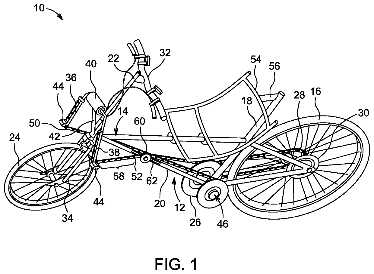
[0038]Referring to the accompanying drawings wherein the same reference numbers refer to the same or similar elements, FIG. 1 shows a recumbent bicycle 10 in accordance with the invention having a double-stroke linear drive mechanism 12 integral with a bicycle frame 14. The recumbent bicycle 10 has many of the standard components found in typical bicycles, such as a rear wheel 16, top tube 18, lower tube 20, steering column 22, front wheel 24, main drive sprocket or sprocket plate 26, main drive chain 28, rear wheel drive sprocket 30, adjustable handlebar 32, and front fork 34. Bicycle 10 may include alternative or other components known to be used on bicycles as long as they do not interfere with the mechanism 12.

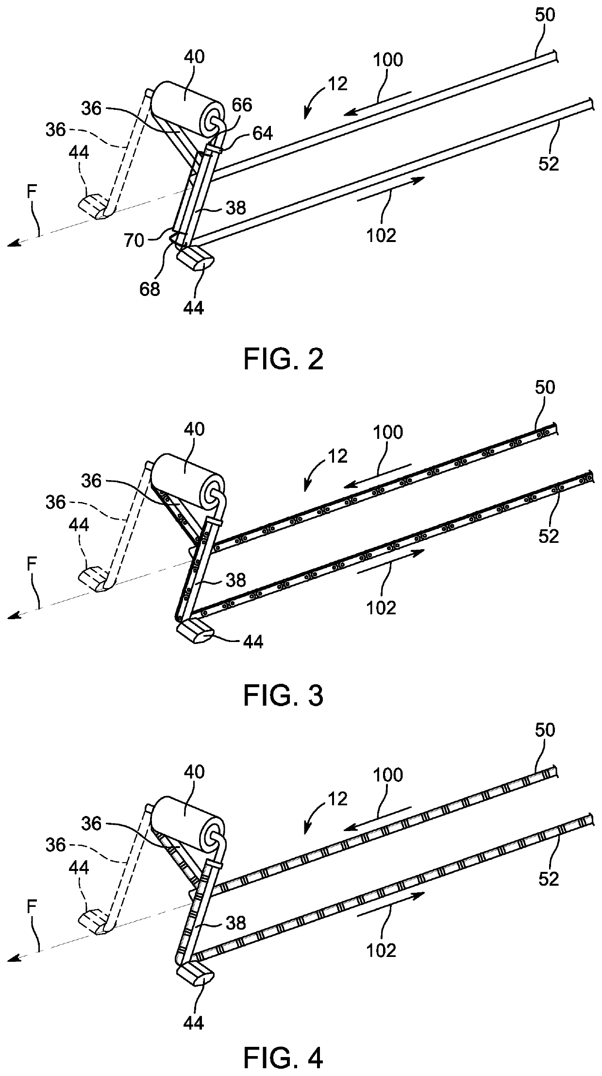
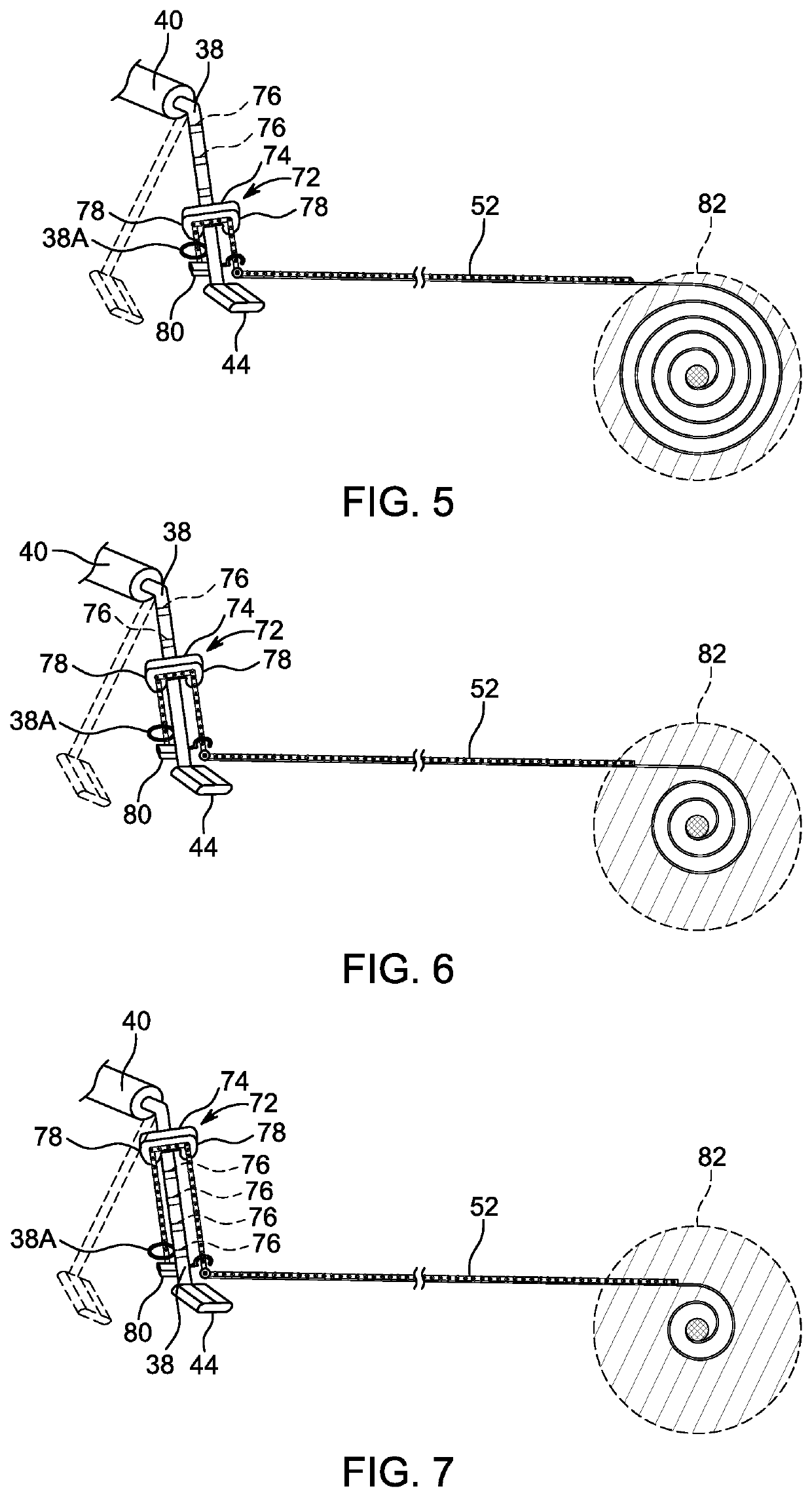
[0039]Bicycle 10 is provided with a right pedal slider 36 and left pedal slider 38, with upper ends of the pedal sliders 36 and 38 joined to a pedal slider bracket 40 of a pedal slider bracket holder 42 of the frame 14 to create a pendulum-type oscillation movement (with t...


PUM


Abstract

Vehicular transmission systems includes a frame, a wheel drive sprocket associated with a wheel, a main drive sprocket mounted on the frame, a transmission member rotationally coupling the drive sprockets, a pedal slider coupled to the frame and which swings forward and rearward, and a drive mechanism including an overrunning clutch system connected to the main drive sprocket. A power link is connected at a first end region to the pedal slider and at a second end region to the clutch system. Forward movement of the pedal slider causes movement of the power link and rotation of the clutch system which causes rotation of the main drive sprocket and the wheel drive sprocket resulting in rotation of the wheel. The clutch system includes a drum over which the power link passes, and which has a circular portion and a fin extending radially outward therefrom.

Description

FIELD OF THE INVENTION[0001]This invention is generally related to recumbent human-powered vehicles such as bicycles, tricycles and other multi-wheel variants that are propelled by a reciprocating thrust motion of the rider using a linear drive mechanism connected by a flexible power link to an overrunning clutch transmission with returning springs. The human-powered vehicle is propelled with the use of pedals which are positioned approximately above and on either side of the front wheel to create a short wheel base in the human-powered vehicle, with the seat located between the front and rear wheels. The human-powered vehicle may be propelled with the thrust motion of one leg, both legs in an alternating motion such as a typical crank-shaft bicycle, or with the use of both legs simultaneously.[0002]The present invention also relates to a transmission system for a vehicle that has an asymmetrically shaped drum which provides increased rotational force when using the vehicle.BACKGROU...

Claims


Application Information

Patent Timeline
Patent Type & Authority Patents(United States)
IPC IPC(8): B62M1/28B62M1/26B62K3/02B62K3/00
CPCB62M1/28B62M1/26B62K3/005B62K3/02
Inventor KIPNIS, MICHAEL
Owner CYCLAZOOM LLC
Why Eureka
Try Eureka