Radiative Wireless Charging System

a wireless charging and wireless charging technology, applied in the direction of electric vehicles, transmission, transportation and packaging, etc., can solve the problems of complex beamforming, poor charging efficiency, and difficulty in aligning the two coils, etc., to achieve efficient wireless charging, high power level, and efficient power transfer

Active Publication Date: 2021-01-14
GOOGLE LLC
View PDF2 Cites 4 Cited by
  • Summary
  • Abstract
  • Description
  • Claims
  • Application Information

AI Technical Summary

Benefits of technology

[0108]The technology is advantageous because it provides for efficient wireless charging. The technology described herein allows a high level of power to be transferred in the near-field region, and at the same time allow the power to quickly attenuate to a low level in the far-field region. This enables efficient power transfer to devices within the near-field region, as well as reduces interference with devices in the far-field region. By automatically focusing electromagnetic waves on detected devices, a user does not need to manually plug in the device to be charged, or align a coil in the device to a coil in a charger. By adjusting operating frequency and other parameters of the wireless charger, the wireless charger may be designed to conveniently fit in everyday environments, such as on or inside furniture, and to charge devices within distances common in practical situations, such as within a meter or so in a room of a residence or office. By using an operating frequency outside of wireless communication ranges, the wireless charger may be able to increase level of power transfer without causing interference with other devices. Aspects of the technology further provides for detection mechanism to avoid transmitting radiation to persons near the wireless charger. The technology further provides for time division for charging multiple devices without requiring extra accessories such as wires, coils, etc.

Problems solved by technology

However, charging efficiency may degrade rapidly with misalignment between the transmitter coil and the receiver coil, yet aligning the two coils may not be easy.
However, complex beamforming may be required to achieve a satisfactory charging efficiency, as well as meeting FCC's safety requirements.

Method used


Image

  • Radiative Wireless Charging System
  • Radiative Wireless Charging System
  • Radiative Wireless Charging System

Examples


Embodiment Construction

Overview

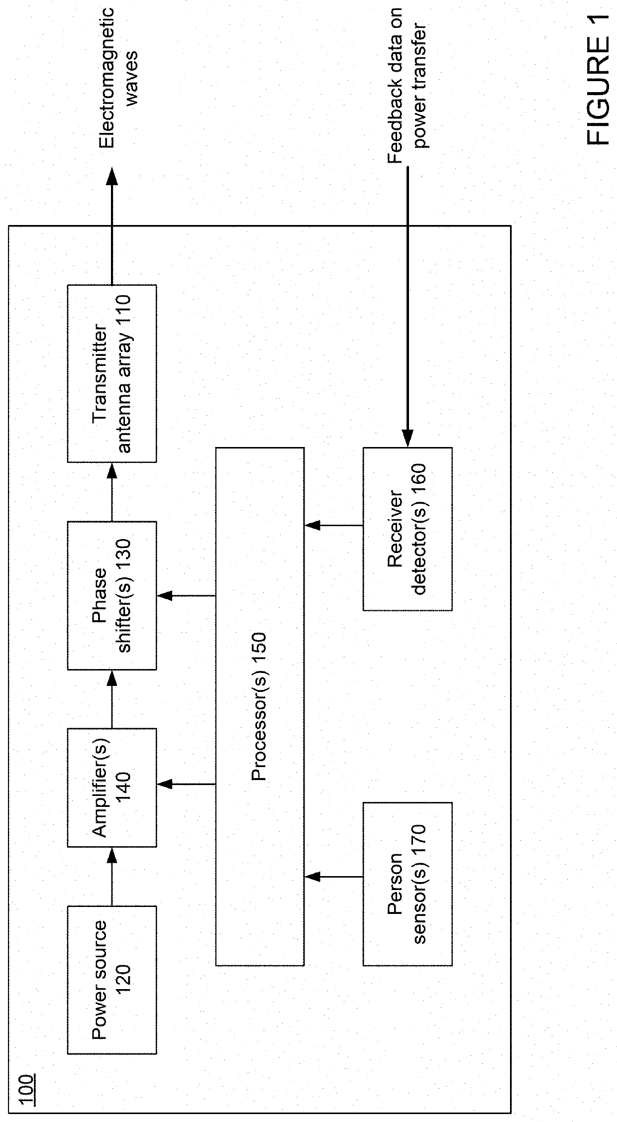
[0032]The technology generally relates to wireless charging. In this regard, a wireless charger may be provided with a transmitter antenna array, one or more detectors, one or more sensors, and one or more processors. The transmitter antenna array may include a plurality of radiating elements configured to transmit power via electromagnetic waves. The detectors may be configured to collect signals from devices that can be wirelessly charged that are located within a vicinity of the wireless charger. The sensors may be configured to collect signals indicating presence of persons located within a vicinity of the wireless charger. The processors may be configured to detect devices and persons in the vicinity of the wireless charger based on the signals from the detectors and the sensors. Based on the detections, the processors may be configured to control the transmitter antenna array to focus electromagnetic waves in one or more beams to charge the detected devices, as well as...


PUM


Abstract

The technology provides for a wireless charger. The wireless charger may have a transmitter antenna array, one or more detectors, one or more sensors, and one or more processors. For instance, the processors may determine, based on signals from the detectors, that one or more receiver antennas are located within a near-field range of the transmitter antenna array. The processors may then control the transmitter antenna array to focus electromagnetic waves on a first receiver antenna of the one or more receiver antennas, and control the transmitter antenna array to transmit power to the first receiver antenna. In some instances, the processors may further determine, based on signals from the sensors, that a person is located within the near-field range of the transmitter antenna array. Based on this determination, the processors may control the transmitter antenna array to stop transmitting power to the first receiver antenna.

Description

CROSS-REFERENCE TO RELATED APPLICATIONS[0001]This application claims the benefit of the filing date of U.S. Provisional Patent Application No. 62 / 872,854 filed Jul. 11, 2019, the disclosure of which is hereby incorporated herein by reference.BACKGROUND[0002]Charging of electronic devices is usually accomplished by plugging devices into a power outlet via charging accessories, such as a charging cable or a holder with contacts. As such, the electronic devices may be required to remain in the vicinity of the outlet, and the number of charging accessories required may scale up with an increasing number of electronic devices that need to be simultaneously charged.[0003]A wireless charger may provide power to a wirelessly charged device without requiring a conductive connection, such as a contact or a wire, between the wireless charger and the wirelessly charged device. For example, an inductive charger may be provided with a transmitter coil for inductively transmitting energy, and the ...

Claims


Application Information

Patent Timeline
Patent Type & Authority Applications(United States)
IPC IPC(8): H02J50/20H04B5/00H02J50/40H02J50/80H02J7/02
CPCH02J50/20H04B5/0037H02J7/02H02J50/80H02J50/402H02J50/23H02J50/40H01Q3/28H01Q3/30H01Q1/22H01Q21/00H02J50/60
Inventor WANG, MAX LI-HUATABESH, MARYAMZHU, JIANG
Owner GOOGLE LLC
Why Eureka
Try Eureka