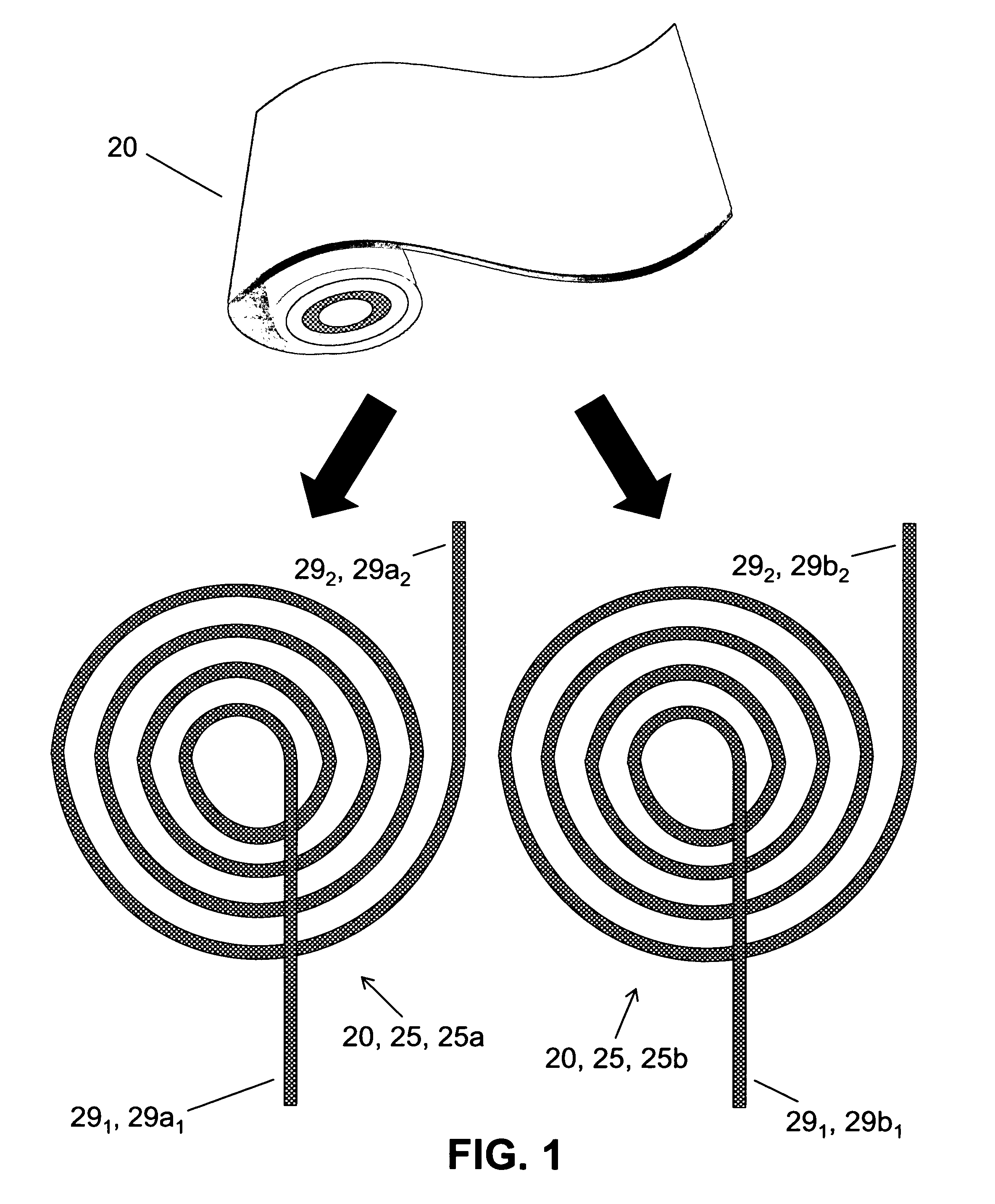
[0009]The acoustic projector in accordance with the present invention bears some similarity to the aforementioned acoustic projector of U.S. Pat. No. 6,570,819. Both acoustic projectors feature a coreless
electromagnetic design and produce coherent,
low frequency, high source-level
underwater acoustic
waves. However, a significant distinction between the '819 acoustic projector and the present invention's acoustic projector is that the former effect an electromagnetic
resonance system only, whereas the latter effects, typically in tandem, both an electromagnetic
resonance system and a
mechanical resonance system. The dual resonance of the inventive acoustic projector (as distinguished from the sole resonance of the '819 acoustic projector) significantly increases the
underwater depth range in which efficient operation is feasible.
[0013]The present invention is typically embodied as an acoustic projector that produces pressure waves underwater. The present invention's acoustic projector as typically embodied produces an underwater
acoustic wave characterized by high efficiency, coherency,
low frequency,
narrow bandwidth, and high acoustic
source level. Inventive practice can achieve enhanced electro-acoustic efficiencies at high powers and at a wide range of depths of operation.
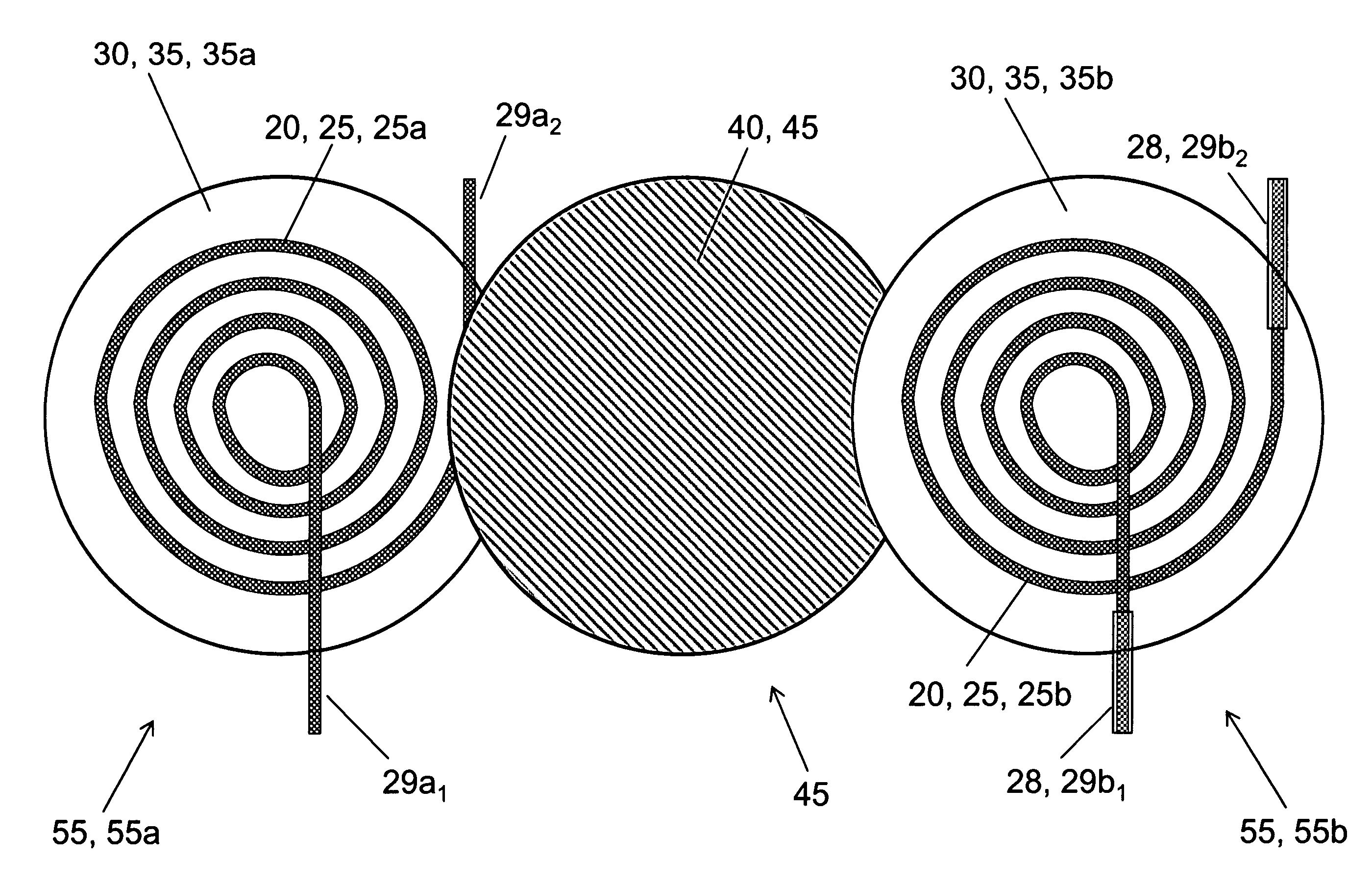
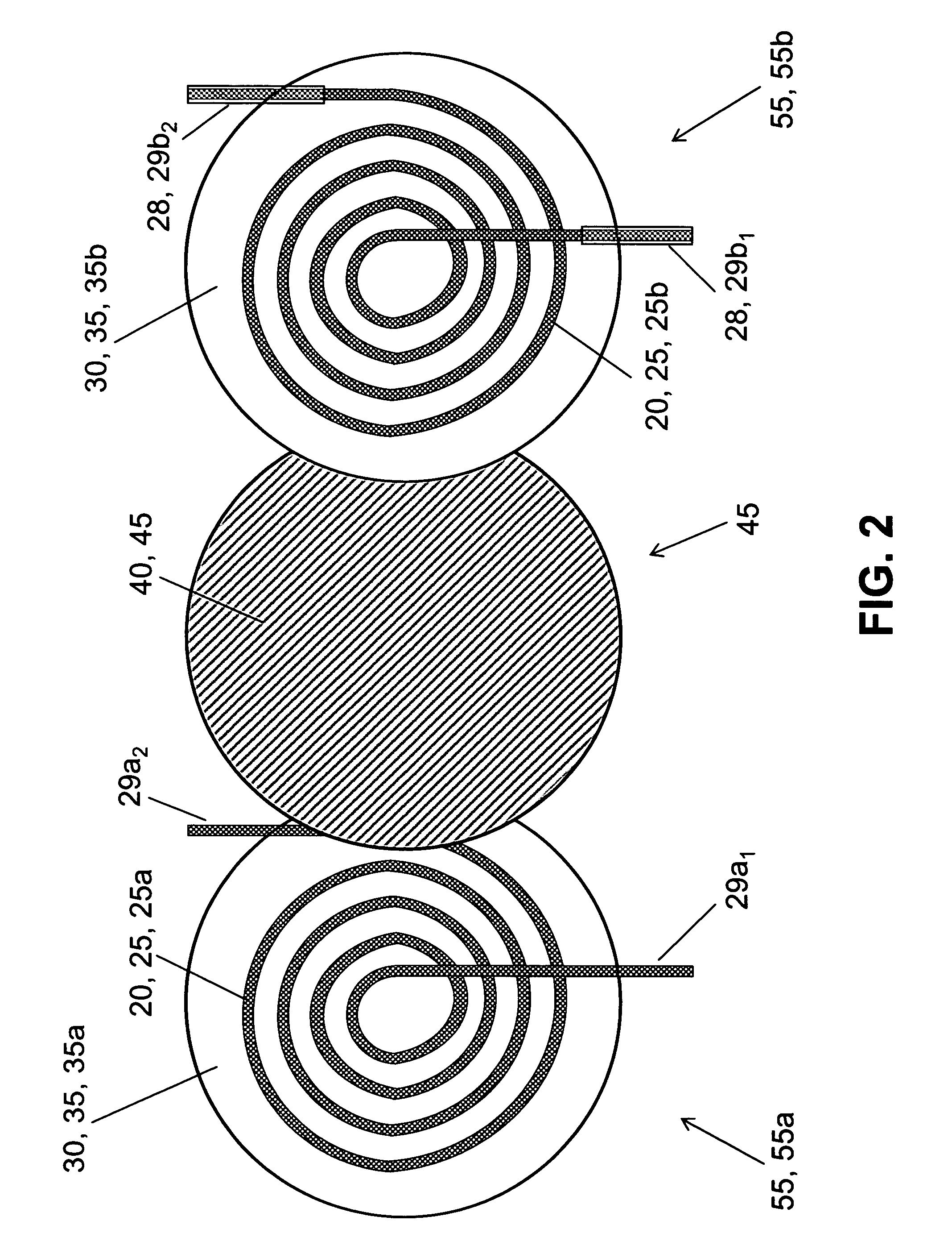
Electrical current produced by a
signal amplifier (which, typically, is connected to and receives its power from a
direct current power source) passes through each coil in opposing directions, creating opposing magnetic fields. Based on the “Lenz Effect,” mechanical forces are generated directly by the opposing electrical currents in the two coils, and without the use of any
magnetic core material. The
inductance of the coil is coupled with
capacitance (at least one
capacitor, such as included in a power
amplifier) to produce a tunable LC electrical circuit. Elastic (“spring-like”) material is used between the coils to produce a tunable spring-
mass system in which
mechanical resonance is associated with the
mass of the entrained water and the spring constant of the elastic material. Either or both of the mechanical circuit (spring-
mass system) and the electrical circuit (
LC circuit) are tuned. Both the mechanical and electrical circuits are driven with a
high current,
low voltage, low-resistance power source, such as a battery or a
current mode amplifier (e.g., one that incorporates fast
solid state switching technology). Inventive practice will frequently benefit from low electrical circuit resistance, a consideration that suggests the inventive implementation of switching-type power amplifiers that operate optimally at low driving voltages and high currents. For instance, based on numerical studies, design specifications have been identified by the present inventors for an inventive acoustic projector that is characterized by ultra
low resistance and that generates an 800 Hz toneburst at a 208 dB
source level with 77% efficiency when used in association with a
low voltage,
high current switching amplifier.
[0014]Through its
mechanical resonance “build-up” process, the present invention's acoustic projector is typically capable of utilizing a small amount of input power to produce high acoustic source levels. The resonance starts out slowly because the input power is low, but gradually builds up to its optimal frequency—i.e., where the electromagnetic resonant frequency and the mechanical resonant frequency are one and the same frequency. Generally speaking, the “
natural frequency” of an elastic object or system is the frequency at which such object or system, once energized, will freely vibrate. Part of this “build-up” process involves an increase in an amount of water that is entrained by the inventive acoustic projector while the inventive acoustic projector continues to resonate. During an initial period, the resonance is entirely or primarily electromechanical in nature; gradually, more and more water is entrained by the overall resonance at a given resonant frequency (which equals the mechanical resonant frequency of the spring-
mass system) as the overall resonance increasingly becomes characterized by mechanical resonant behavior in addition to the electromagnetic resonant behavior with which it is initiated at the same resonant frequency. When the preset invention's spring-
mass system is completely energized, it completely “finds” its mechanically resonant frequency (
natural frequency). The present invention's mechanical resonance thereby joins with the present invention's electromagnetic resonance to strengthen the resonance (vibration or oscillation) significantly beyond that which is generated by the present inventors' '819 acoustic projector, which relies solely on electromagnetic resonance. The finer the tuning of the mechanical resonance and the electromagnetic resonance with respect to each other, the greater the efficiency of this electrical-to-mechanical power transfer.
[0015]The present invention's acoustic projector uses elastic material to create a resonant spring-mass behavior, whereas the present inventors' '819 acoustic projector does not; therefore, in contrast to typical embodiments of the present inventors' '819 acoustic projector, typical embodiments of the inventive acoustic projector work well at greater depths, e.g., at depths below twenty feet. The present invention's water depth versatility also stands in contrast to conventional “boomer” piezoelectric acoustic projectors, which are positioned at or just below the water surface. In some ocean environments, only a small amount of energy from a pulse generated at / near the surface will reach the bottom, due to the sound velocity profile (SVP) bending of the sound up towards the surface. Since the present invention can be used in
deep water (even at the water bottom), the
noise level entering the bottom layer of the body of water is much higher. In addition, there is less
distortion in the receiving
signal, since the sound source is closer to the bottom. Moreover, the present invention typically uses less power and operates at a lower
source level, the latter being environmentally advantageous for marine mammals (e.g., whales, dolphins, porpoises, seals, walruses, sea lions, manatees, dugongs, polar bears) that are sensitive to loud
underwater noise. Furthermore, the present invention typically provides a coherent, ultra repeatable
signal, transient or
steady state, which can be beneficial for
signal processing.
[0016]Conventional
low frequency underwater acoustic projectors operate in the 30 Hz-1 kHz range. The present invention's acoustic projector can be embodied as suitable for underwater use inside and / or outside of this frequency range. As compared with conventional low frequency acoustic projectors, the present invention's acoustic projector can be embodied as a very small device that is capable of producing high source levels of low
frequency sound. In order to be used with a battery (
direct current power source), a conventional piezoelectric projector requires complicated electrical circuitry and heavy transformers to transform the power to a
high voltage and low current; some power is lost in this transformation, and space is needed for the
electronics. The present invention obviates power conversion
electronics, thus simplifying design and reducing weight and space. The present invention's acoustic projector can be manufactured inexpensively and can be utilized as a battery-operated, throw-away device. One inventive acoustic projector can be used, or plural (e.g., multiple) inventive acoustic projectors can be used in combination with one or more other inventive acoustic projectors in an array. Nor is the inventive device's utility relegated to acoustic projection, as it can be embodied, for instance, as a mechanical
shaker.

