Supercharge Your Innovation With Domain-Expert AI Agents!

Gas turbine engine stator vane base shape

a technology of gas turbine engines and base shapes, which is applied in the direction of engine manufacture, machines/engines, stators, etc., can solve the problems of vibration, high pressure, and high temperature of the stator vanes

Active Publication Date: 2022-03-29
RTX CORP
View PDF11 Cites 0 Cited by
  • Summary
  • Abstract
  • Description
  • Claims
  • Application Information

AI Technical Summary

Benefits of technology

The patent describes a way to attach a stator vane to a conical stator shroud in a gas turbine engine. The method ensures that the stator vane is securely attached to the stator shroud, and that the vane is positioned correctly for optimal performance. This technique improves the manufacturing process of stator assemblies for gas turbine engines.

Problems solved by technology

The stator vanes are subjected to high pressures, high temperatures, and vibrations that may be transmitted to the case.

Method used


Image

  • Gas turbine engine stator vane base shape
  • Gas turbine engine stator vane base shape
  • Gas turbine engine stator vane base shape

Examples


Embodiment Construction

[0033]A detailed description of one or more embodiments of the disclosed apparatus and method are presented herein by way of exemplification and not limitation with reference to the Figures.

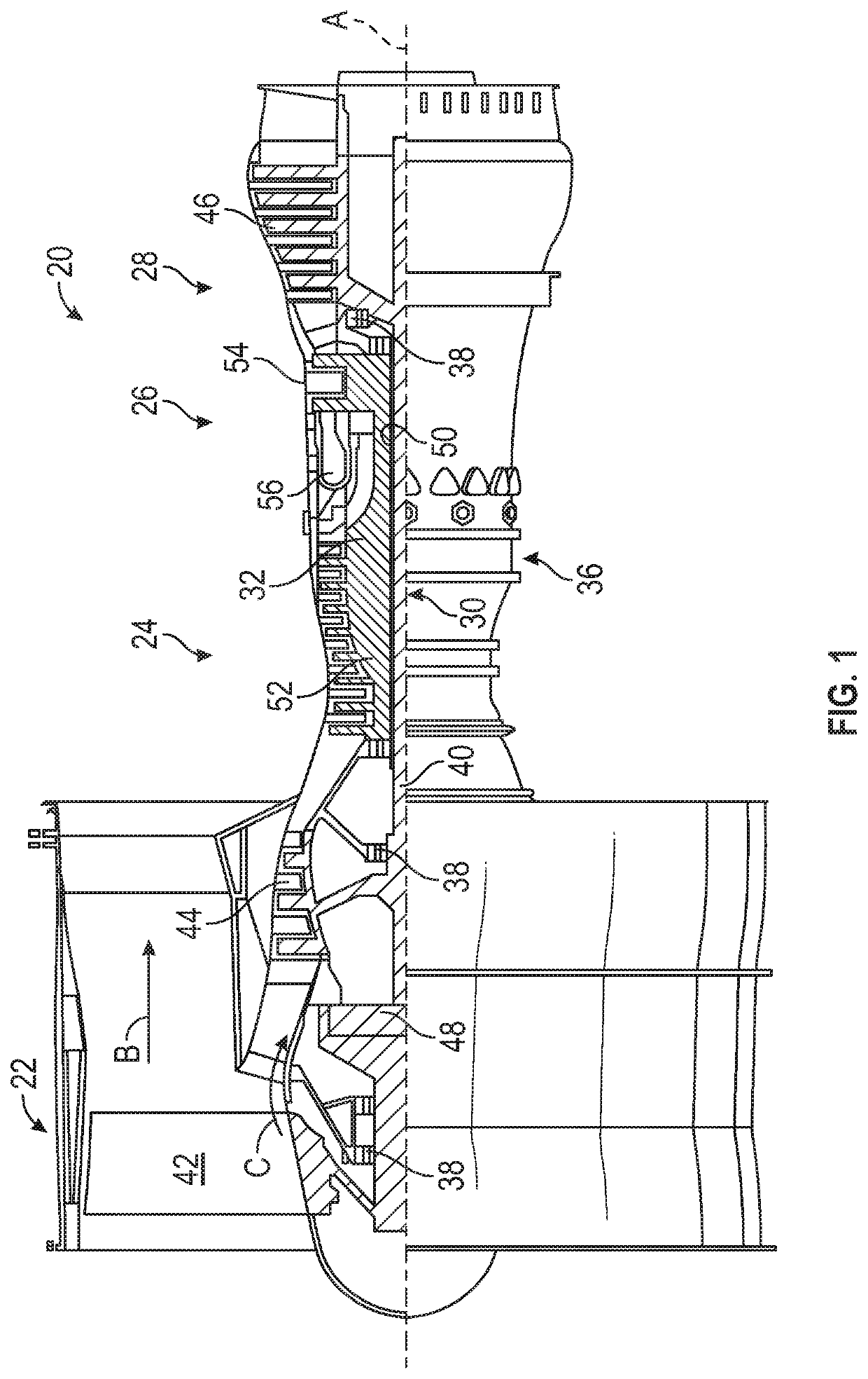
[0034]FIG. 1 schematically illustrates a gas turbine engine 20. The gas turbine engine 20 is disclosed herein as a two-spool turbofan that generally incorporates a fan section 22, a compressor section 24, a combustor section 26 and a turbine section 28. Alternative engines might include an augmentor section (not shown) among other systems or features. The fan section 22 drives air along a bypass flow path B in a bypass duct, while the compressor section 24 drives air along a core flow path C for compression and communication into the combustor section 26 then expansion through the turbine section 28. Although depicted as a two-spool turbofan gas turbine engine in the disclosed non-limiting embodiment, it should be understood that the concepts described herein are not limited to use with two-spool...


PUM


Abstract

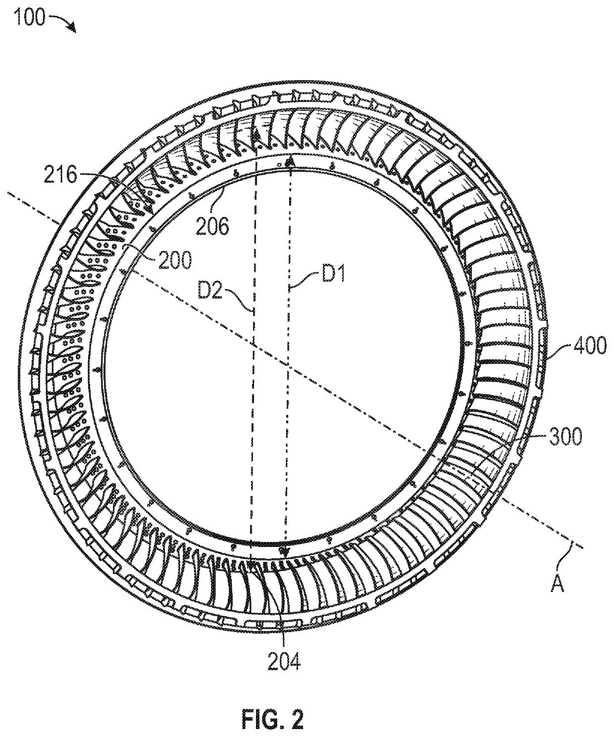
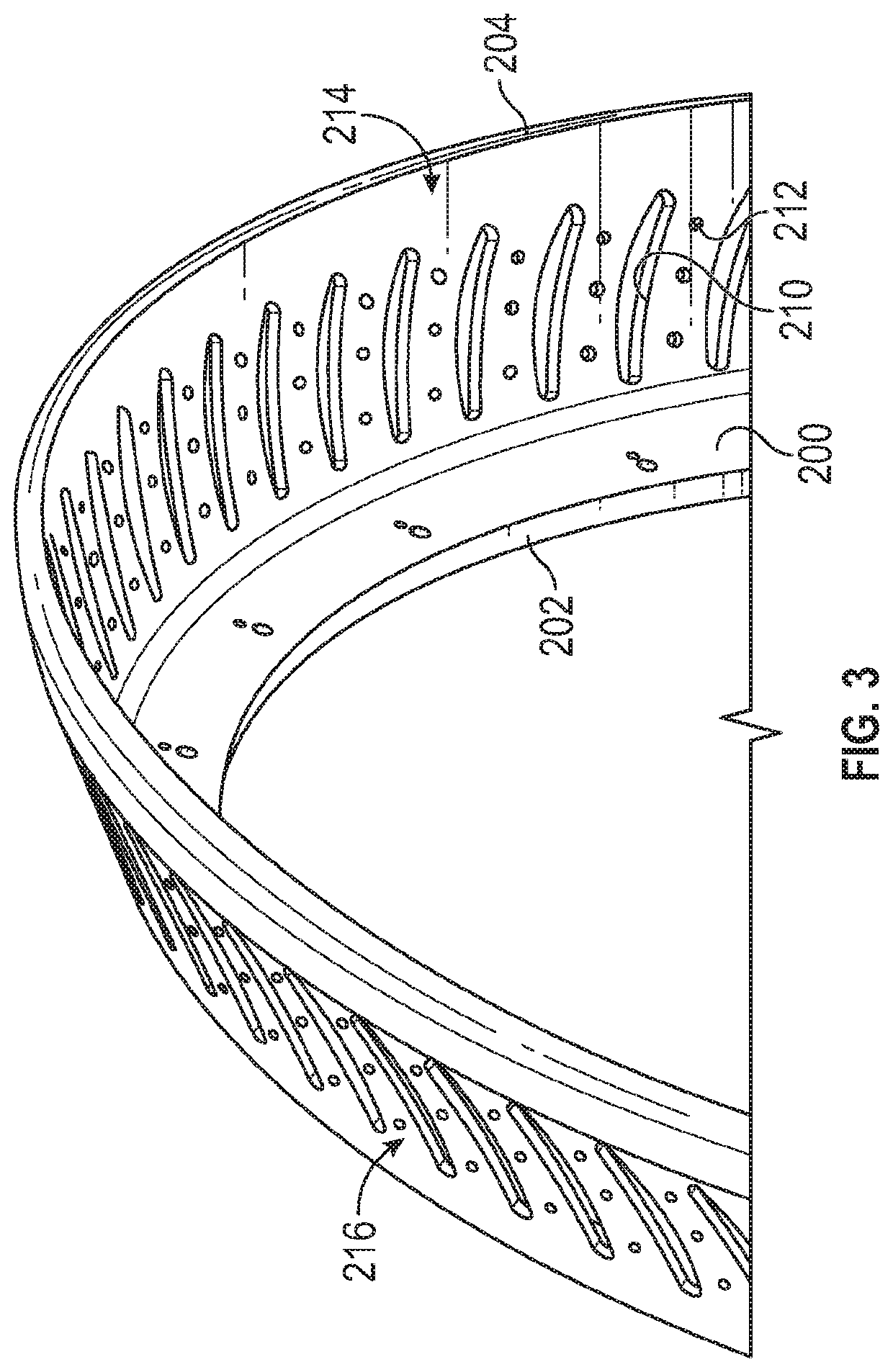
A stator assembly for use in a gas turbine engine is provided. The stator assembly including: a conical stator shroud including a radially inward surface and a radially outward surface opposite the radially inward surface; and a plurality of stator vanes integrally attached to the conical stator shroud, each of the plurality of stator vanes being integrally attached to the conical stator shroud at a base of the stator vane, wherein radially outward surface of the base of the stator vane mates flush with the radially inward surface of the conical stator shroud.

Description

BACKGROUND[0001]The subject matter disclosed herein generally relates to gas turbine engines and, more particularly, to a guide vanes of gas turbine engines.[0002]The gas turbine engine may include a core that is supported by a case. The core may include stator vanes that are supported by the case to limit displacement of the stator vanes. The stator vanes are subjected to high pressures, high temperatures, and vibrations that may be transmitted to the case.SUMMARY[0003]According to one embodiment, a stator assembly for use in a gas turbine engine is provided. The stator assembly including: a conical stator shroud including a radially inward surface and a radially outward surface opposite the radially inward surface; and a plurality of stator vanes integrally attached to the conical stator shroud, each of the plurality of stator vanes being integrally attached to the conical stator shroud at a base of the stator vane, wherein radially outward surface of the base of the stator vane m...

Claims


Application Information

Patent Timeline
Patent Type & Authority Patents(United States)
IPC IPC(8): F01D9/04
CPCF01D9/042F01D9/041F05D2230/60F05D2240/12F05D2250/232
Inventor HUNNEWELL, NICHOLASMARTEL, MICHAEL J.
Owner RTX CORP
Features
  • R&D
  • Intellectual Property
  • Life Sciences
  • Materials
  • Tech Scout
  • Unparalleled Data Quality
  • Higher Quality Content
  • 60% Fewer Hallucinations
Learn More