Initiator unit

a technology of initiator unit and bare wire end, which is applied in the direction of blasting, blasting cartridge, weapon components, etc., can solve the problems of increasing the amount of labor required, and reducing the safety of electric matches

Active Publication Date: 2022-03-29
HADDON TIMOTHY
View PDF14 Cites 0 Cited by
  • Summary
  • Abstract
  • Description
  • Claims
  • Application Information

AI Technical Summary

Benefits of technology

[0015]The invention is distinctly characterised by the specific configuration of the engagement module and the cooperable configuration of the shunt module, so that the shunt module can be releasably engaged to the engagement module in order to close the circuit by creating a shunt connection between the first and second electrical conductors in the engagement module. With the shunt module in position engaged to the engagement module, a conductive connection is created between the first connector contact portion and the first shunt contact portion, a further conductive connection is created between the second connector contact portion and the second shunt contact portion, a closed circuit is created by the conductive shunt connection, and the electronic actuator is effectively shunted for safety.
[0016]This confers two advantages in particular relative the conventional shunting of an electronic actuator by the physical twisting together of connecting wires. First, a more consistent shunt connection is readily created for safe transport. Second, the removal of the shunt module frees up the engagement module to be engaged via a suitable complementary receiving structure on or in association with a firing control board to facilitate the assembly of multiple electronic initiator units as part of a firing control system.
[0019]The engagement module and the shunt module conveniently further comprise a protective and insulating housing in which the respective first and second connectors are housed and electrically isolated from each other. The respective housings of the engagement module and the shunt module are preferably co-operably structured to facilitate their mutual mechanical engagement and configured so as to effect the required electrical connection when so engaged. For example, the respective housings comprise mutually engageable projecting and recessed portions which facilitate the releasable engagement together of the two housings and additionally facilitate the location and electrical connection between the first connector contact portion and the first shunt contact portion and between the second connector contact portion and the second shunt contact portion.
[0027]The provision of a shunt module mechanically and electrically engageable to the engagement module in the manner above described confers two functional advantages.
[0028]First, engagement of the shunt module creates an effective and stable shunt connection for safety. The shunt connection is more consistently and easily provided, by attachment of the shunt module, than is the case where bare wires are twisted together. The shunt connection is not readily compromised. It requires active removal of the shunt module by pulling the two modules apart.

Problems solved by technology

The provision of bare wire ends on the two connecting wires of the electric match presents a potential hazard both during transport and at certain stages of assembly.
The twisting, bending or folding of the ends of the wires to create a closed loop for shunting is a time-consuming and labour intensive process and does not necessarily guarantee consistent shunt connection.
As pyrotechnic displays grow more complex, this additional labour becomes significant.

Method used


Image

  • Initiator unit
  • Initiator unit
  • Initiator unit

Examples


Embodiment Construction

[0054]The specific details of the single embodiment or variety of embodiments described herein are to the described system and methods of use. Any specific details of the embodiments are used for demonstration purposes only, and no unnecessary limitations or inferences are to be understood therefrom.

[0055]Before describing in detail exemplary embodiments, it is noted that the embodiments reside primarily in combinations of components and procedures related to the system and method. Accordingly, the system components have been represented where appropriate by conventional symbols in the drawings, showing only those specific details that are pertinent to understanding the embodiments of the present disclosure so as not to obscure the disclosure with details that will be readily apparent to those of ordinary skill in the art having the benefit of the description herein.

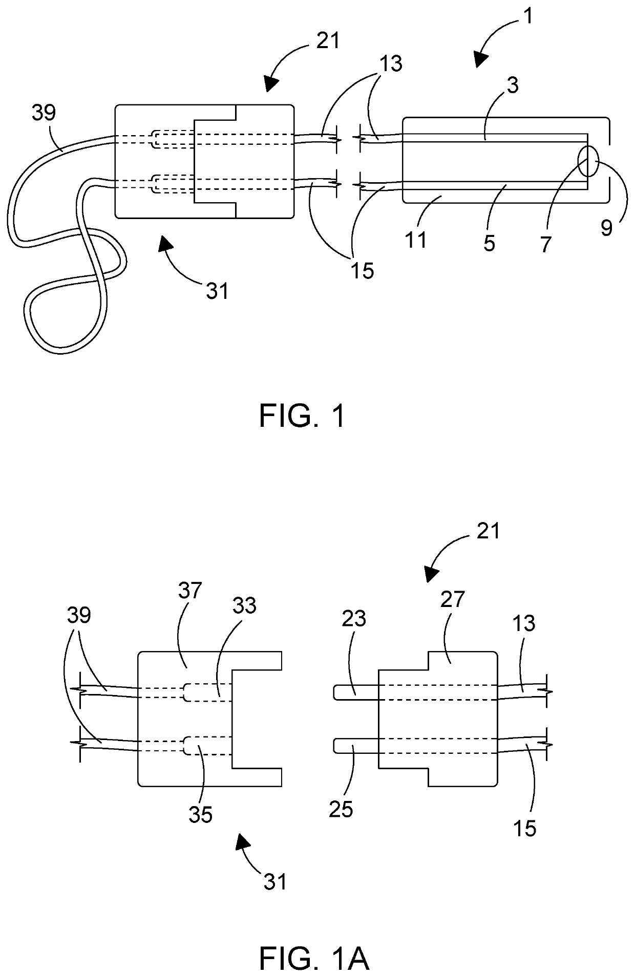
[0056]FIG. 1 shows an assembled unit in accordance with the principles of the invention in side view, with an electric...


PUM


Abstract

An electronic initiator unit for the electrical firing of a charge in an energetic device is described. The unit includes an actuation module comprising electrically in series a first conductor, an electronic actuator, and a second conductor; an engagement module including a first electrical connector conductively connected to the first conductor and defining a first connector contact portion spaced remotely from the first conductor and a second electrical connector conductively connected to the second conductor and defining a second connector contact portion spaced remotely from the second conductor; a shunt module including a first shunt connector defining a first shunt contact portion, a second shunt connector defining a second shunt contact portion, and a conductive shunt connection between the first and second shunt connector spaced remotely from the shunt contact portions; wherein the engagement module and the shunt module are co-operably configured so as to be engageable together such as to effect when so engaged an electrical connection between the first connector contact portion and the first shunt contact portion and between the second connector contact portion and the second shunt contact portion. A system and method for the electrical firing of a charge in a plurality of energetic devices in a controlled manner from a remote location are also described.

Description

CROSS-REFERENCE TO RELATED APPLICATIONS[0001]The present invention claims priority to PCT application number PCT / GB2017 / 053333 filed on Nov. 7, 2017 entitled “INITIATOR UNIT” the entire disclosure of which is incorporated by reference herein.TECHNICAL FIELD[0002]The invention relates to an electronic initiator unit for the electrical filing of a charge in an energetic device.[0003]In particular the invention relates to an electronic initiator unit for use in an electrical firing system to give the ability to fire single or multiple charges in single of multiple energetic devices in a controlled manner from a remote location. The invention also relates to such an electrical firing system including a plurality of electronic initiator units and a suitable firing control means. The invention for example relates to an electronic initiator unit or electrical firing system for pyrotechnic devices, and is discussed accordingly by way of example herein, but can be seen to be applicable to an...

Claims


Application Information

Patent Timeline
Patent Type & Authority Patents(United States)
IPC IPC(8): F42B3/182F42D1/045F42B4/00
CPCF42B3/182F42D1/045F42B4/00F41A19/69F42B3/12
Inventor HADDON, TIMOTHY
Owner HADDON TIMOTHY
Why Eureka
Try Eureka