Collection tank for sump pump under building floor

a technology of collecting tank and sump pump, which is applied in the field of collecting tank, can solve problems such as interference with effective operation, and achieve the effect of minimizing the collection of gravel particles and passing quickly

Active Publication Date: 2022-04-19
LYON HLDG LTD
View PDF7 Cites 0 Cited by
  • Summary
  • Abstract
  • Description
  • Claims
  • Application Information

AI Technical Summary

Benefits of technology

[0012]By arranging each hole so that the inner peripheral edge of the hole is elevated at the lowermost point thereof relative to the lowermost point of the outer peripheral edge of the hole, each hole is effectively inclined upwardly and inwardly from the exterior to the interior of the tank. This allows water to readily pass through the hole while preventing gravel particles from readily passing through the hole to minimize the collection of gravel particles within the collection tank.

Problems solved by technology

Commonly used gravel below the floor of a building includes a particle size which may be smaller than the perforated holes in the walls of the collection tank such that some of the gravel particles may also pass through the holes into the interior of the collection tank in a manner which may interfere with effective operation of the sump pump.

Method used


Image

  • Collection tank for sump pump under building floor
  • Collection tank for sump pump under building floor
  • Collection tank for sump pump under building floor

Examples


Embodiment Construction

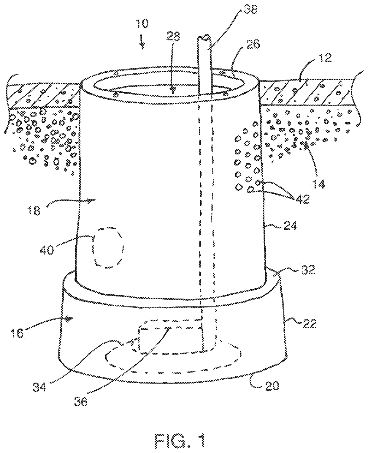
[0027]Referring to the accompanying figures there is illustrated a collection tank generally indicated by reference numeral 10. The collection tank is particularly suited for use below the floor 12 of a building. The collection tank is typically surrounded with a granular aggregate material 14 such as gravel that occupies a space below the floor of the building.

[0028]Although two embodiments of the collection tank are illustrated in the accompanying figures, the features in common with both embodiments will first be described herein.

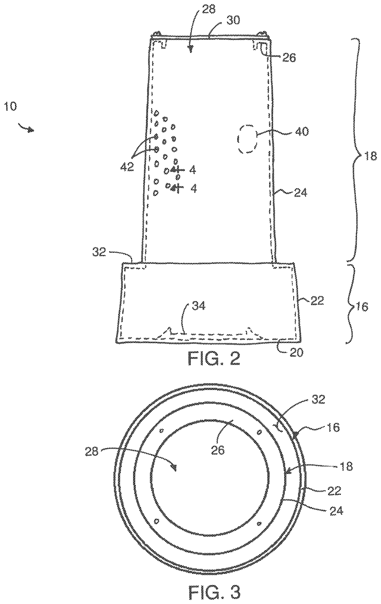
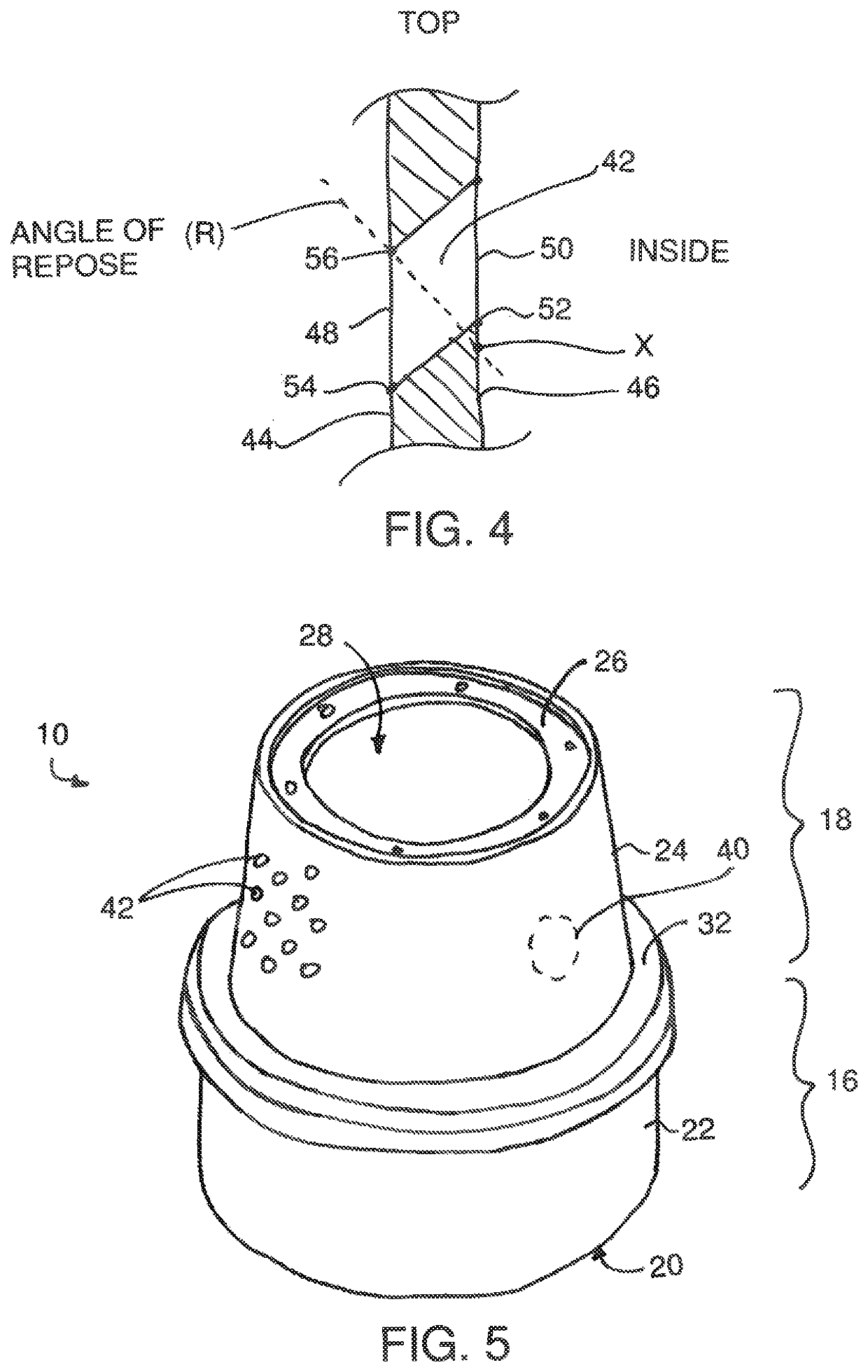
[0029]In each instance the collection tank 10 comprises a tank body having a lower tank portion 16 forming the bottom of the tank 10 and an upper tank portion 18 forming the top of the collection tank. The lower tank portion has a hollow interior which is open at the top end thereof. The upper tank portion 18 includes a similar hollow interior, but is open at the bottom and so that the upper and lower tank portions openly communicate with one another and...


PUM


Abstract

A collection tank for mounting in a bed of gravel particles under a floor of a building for collecting ground water from an area under the floor has a tank body including a lower tank portion and an upper tank portion. The lower tank portion defines a container for collected water with an open top. The upper tank portion has an outer wall upstanding from the open top of the lower tank portion, in which the outer wall is perforated with holes for passage of ground water into the tank body. Each of the holes extends radially through the outer wall of the upper tank portion at an upward slope so as to minimize entry of surrounding gravel particles into the tank body through the holes.

Description

[0001]This application claims the benefit under 35 U.S.C. 119 (e) of U.S. provisional application Ser. No. 62 / 890,356, filed Aug. 22, 2019.FIELD OF THE INVENTION[0002]The present invention relates to collection tank placed under a floor of a building to collect water from an area under the floor and which is capable of receiving a sump pump to pump the collected water from the collection tank away from the building.BACKGROUND[0003]A common arrangement for a building is to provide a series of weeping tiles in the form of perforated drainage piping about the perimeter and below the floor of the building which collect groundwater and direct the groundwater into a sump pit. A typical sump pit comprises a collection tank mounted in the ground below the floor of the building in connection with the weeping tile to collect water from the perimeter and below the floor of the building into the collection tank. A sump pump is mounted in the collection tank for pumping collected water through a...

Claims


Application Information

Patent Timeline
Patent Type & Authority Patents(United States)
IPC IPC(8): E03B3/06E02B11/00
CPCE03B3/06E02B11/00E03F5/22
Inventor CASCIANO, PAUL
Owner LYON HLDG LTD
Why Eureka
Try Eureka