
Pneumatic tire

a technology of pneumatic tires and land sections, which is applied in the direction of tyre tread bands/patterns, vehicle components, transportation and packaging, etc., can solve the problems of deterioration such as wear in the land section, and the rigidity of the land section in the tread is reduced, so as to achieve the effect of not reducing the rigidity of the land section in the tread

Active Publication Date: 2022-05-03
TOYO TIRE & RUBBER CO LTD
View PDF8 Cites 0 Cited by
  • Summary
  • Abstract
  • Description
  • Claims
  • Application Information

AI Technical Summary

Benefits of technology

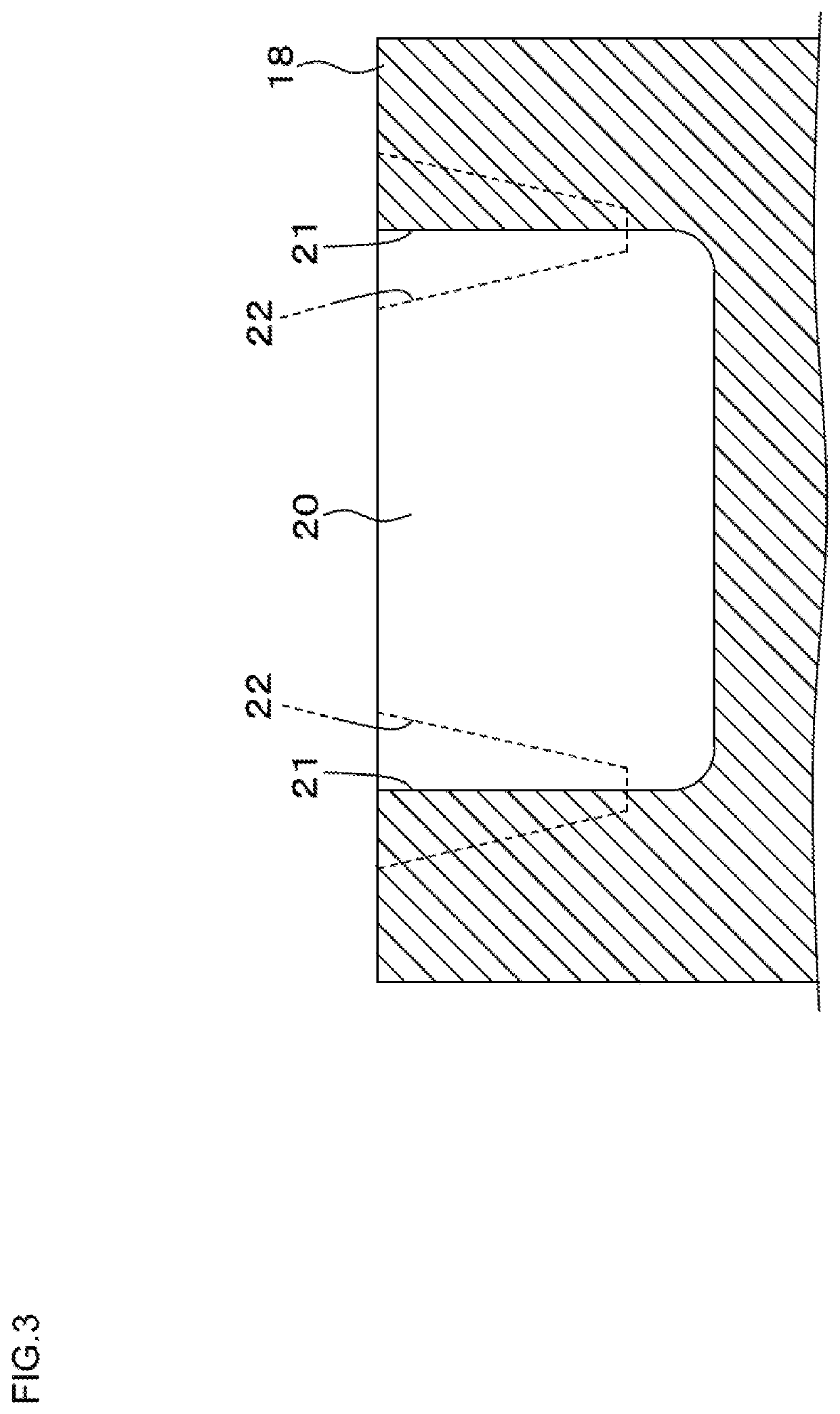
The present invention relates to a pneumatic tire that addresses the problem of reduced rigidity of the land section in the tread due to cracks starting from end parts in the extending direction of sipes. The invention provides a tire design that prevents these cracks and maintains the rigidity of the land section in the tread. This is achieved by eliminating the formation of cylindrical holes at the end parts in the extending direction of sipes. The diameter of the holes is smaller as coming towards the deeper position, which allows for a gradual reduction in rigidity of the land sections in the tread.

Problems solved by technology

However, as a result that the cylindrical holes are formed at end parts in the extending direction of sipes, there is a problem that rigidity of the land section in the tread is reduced.
The reduction in rigidity of the land section in the tread causes deterioration such as wear in the land section.

Method used


Image

  • Pneumatic tire
  • Pneumatic tire
  • Pneumatic tire

Examples


Embodiment Construction

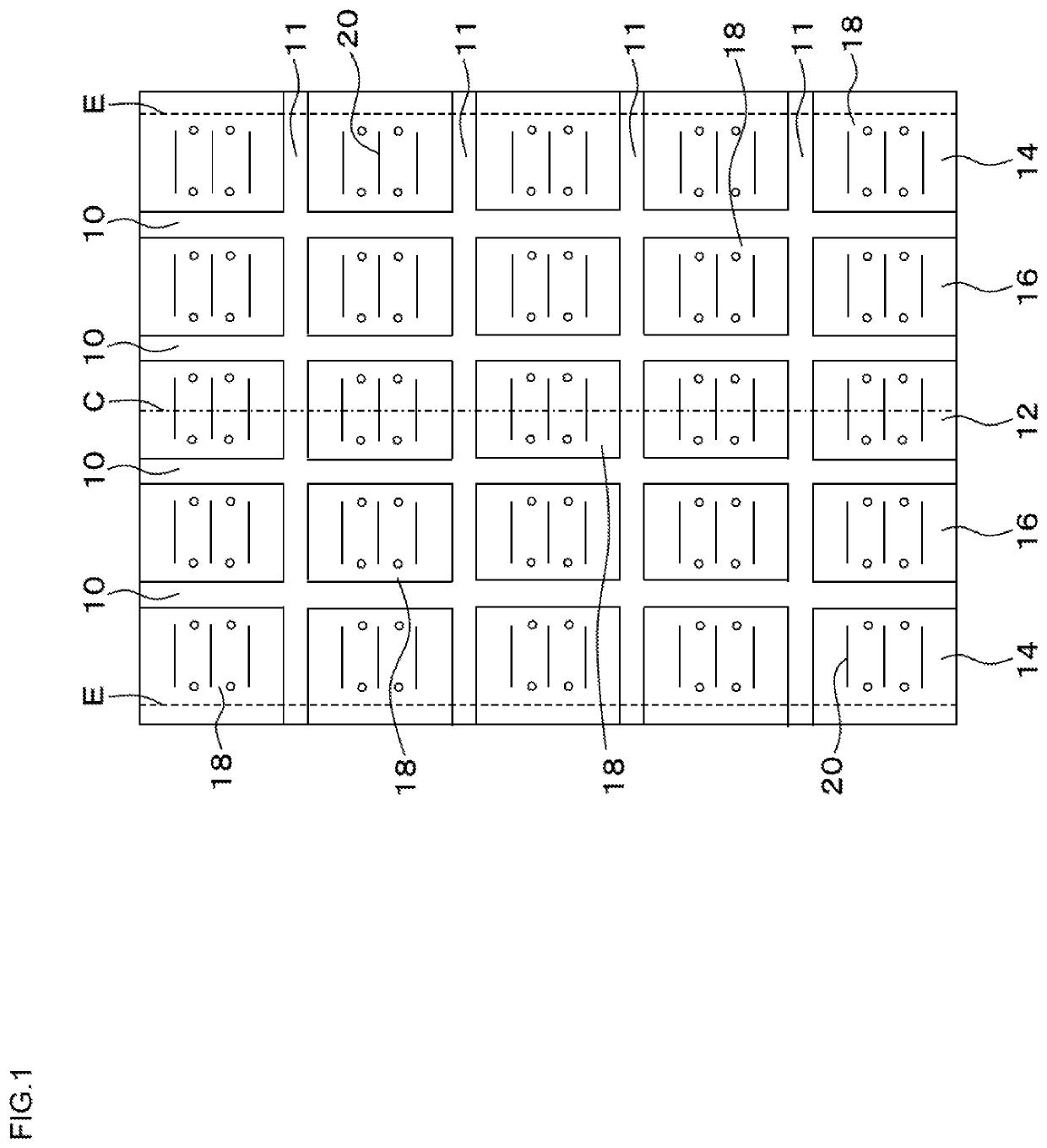
[0021]A structure of a pneumatic tire according to an embodiment will be explained with reference to the drawings. A brand-new unworn pneumatic tire will be explained below unless otherwise particularly mentioned. A heavy load tire fitted to a truck or a bus is assumed to be used as an example of the pneumatic tire according to the embodiment. A studless tire fitted at the time of traveling on an icy road is also assumed to be used as an example of the pneumatic tire according to the embodiment.

[0022]A general cross-sectional structure of the pneumatic tire according to the embodiment is as follows. First, bead sections are provided on both sides in a tire width direction and carcass plies are folded from an inner side to an outer side in the tire width direction to wrap the bead sections and form a skeleton of the pneumatic tire. A plurality of belts are provided on an outer side in a tire radial direction of the carcass plies, and a tread having a ground contact surface on an oute...


PUM


Abstract

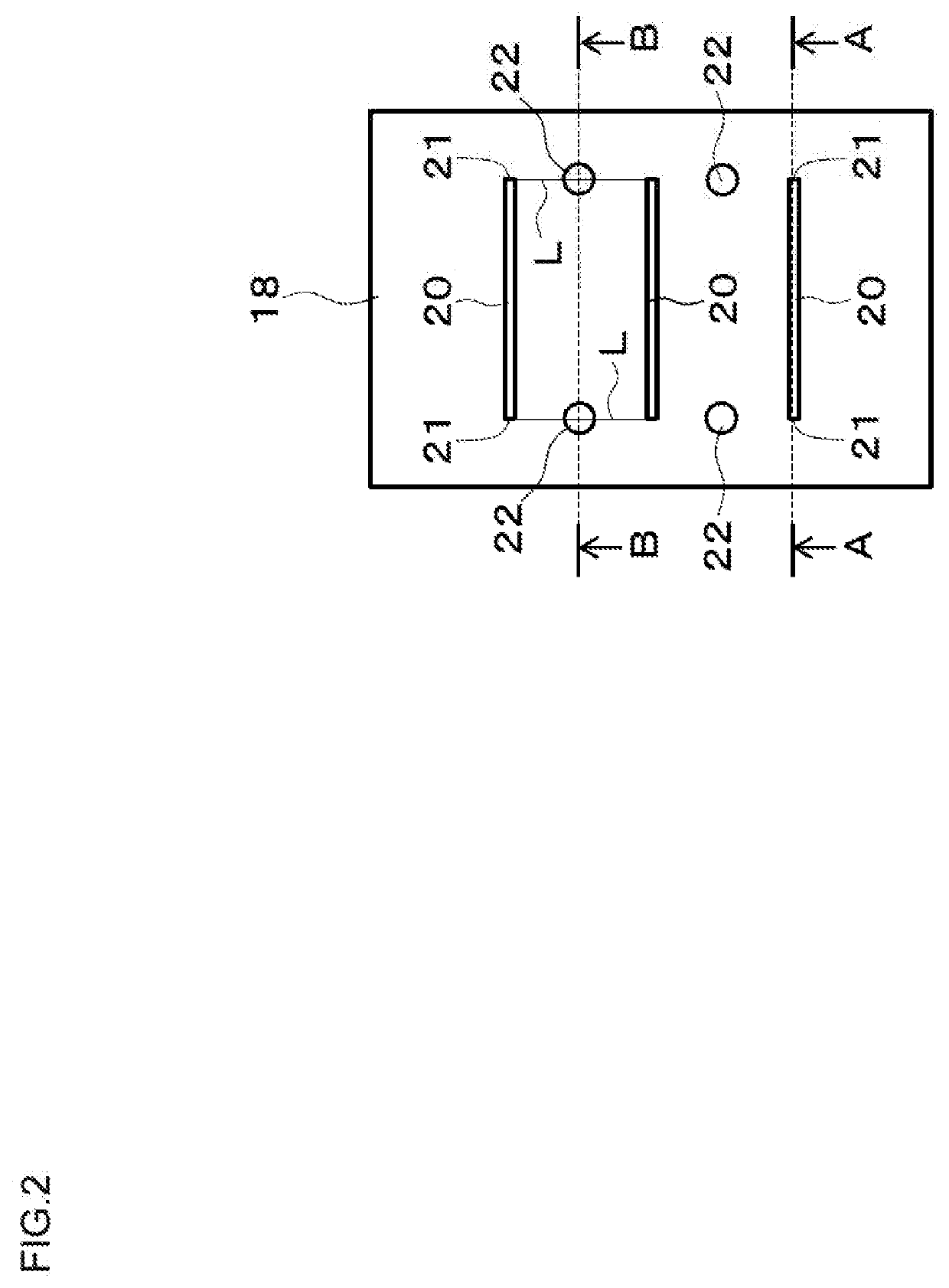
A pneumatic tire in which a plurality of sipes 20 are formed in land sections of a tread and at least one of end parts in an extending direction of each sipe 20 is an end part 21 in the land section that is blocked in the land section, in which holes 22 separated from the sipes 20 are formed on line segments L connecting the end parts 21 in the land section of adjacent two sipes 20 to each other, and the hole 22 has a circular shape or an elliptical shape in plan view, a diameter of which becomes smaller as coming toward a deeper position.

Description

CROSS-REFERENCE TO RELATED APPLICATION[0001]The present application claims priority from Japanese patent application No. 2018-124938 on the basis of Japanese patent application No. 2018-124938 (filing date: Jun. 29, 2018). The entire contents of Japanese patent application No. 2018-124938 is hereby incorporated into the present application by reference of Japanese patent application No. 2018-124938.TECHNICAL FIELD[0002]The present invention relates to a pneumatic tire.BACKGROUND ART[0003]In order to improve braking and driving performance and for other purposes, ripen are formed on land sections of a tread in a pneumatic tire in related art. However, stress is concentrated on end parts in an extending direction of sipes, therefore, cracks tend to occur from the end parts as starting points.[0004]In response to the above, circular holes with a larger diameter (not a radiu) than a sipe width in plan view are formed at end parts in the extending direction of the sipes in related art (f...

Claims


Application Information

Patent Timeline
Patent Type & Authority Patents(United States)
IPC IPC(8): B60C11/03B60C11/12B60C11/11
CPCB60C11/032B60C11/0306B60C11/1204B60C11/1236B60C11/1259B60C11/11B60C2011/1209B60C2011/1254B60C2011/1227B60C2011/1268
Inventor NISHIO, TAIICHI
Owner TOYO TIRE & RUBBER CO LTD
Learn More