Method for detecting a malfunction of a voltage-limiting circuit and control system for implementing said malfunction-detecting method

a voltage-limiting circuit and malfunction-detecting technology, applied in the direction of electric control, machines/engines, instruments, etc., can solve the problems of not being able to detect the malfunction of the piezoelectric injector of the engine of the motor vehicle, and the electronic components of the control system are no longer protected

Active Publication Date: 2022-05-10
VITESCO TECH GERMANY GMBH
View PDF12 Cites 0 Cited by
  • Summary
  • Abstract
  • Description
  • Claims
  • Application Information

AI Technical Summary

Benefits of technology

[0009]The objective of the present invention is to overcome all or some of the limitations of the solutions of the prior art, notably those discussed hereinabove, by proposing a solution which makes it possible to detect a malfunction of a voltage-limiting circuit of a control system for controlling capacitive actuators of a motor vehicle, such as piezoelectric injectors.
[0012]controlling the control circuit to charge said capacitor for a predefined period to make it possible, in the absence of a malfunction of the voltage-limiting circuit, for the output voltage to reach the theoretical maximum value,
[0016]The detection method then includes controlling the control circuit to charge the capacitor, for a sufficient period to make it possible, in the absence of a malfunction of the voltage-limiting circuit, for the output voltage to reach the theoretical maximum value. Such a period may easily be deduced from the value of the capacitance at the output port when all the capacitive actuators are disconnected.
[0019]Such arrangements therefore make it possible to detect a malfunction of the voltage-limiting circuit without necessarily adding electronic components with respect to the prior art. Notably, the electronic components used to measure the output voltage, which is used according to the prior art to detect a malfunction at a capacitive actuator, may be reused to detect a malfunction of the voltage-limiting circuit. Furthermore, certain control circuits according to the prior art already include a capacitor between their output port and electrical ground, for purposes of protection against electrostatic discharges.

Problems solved by technology

Furthermore, it is possible, by measuring the output voltage and by comparing it to the theoretical maximum value, to detect the malfunction (open circuit) at the piezoelectric injector since, in the absence of a malfunction, the charging period should not make it possible for the output voltage to reach the theoretical maximum value.
However, in case of a malfunction of the voltage-limiting circuit, the electronic components of the control system are no longer protected and, furthermore, it is then no longer possible to detect a malfunction of the piezoelectric injectors of the engine of the motor vehicle.

Method used


Image

  • Method for detecting a malfunction of a voltage-limiting circuit and control system for implementing said malfunction-detecting method
  • Method for detecting a malfunction of a voltage-limiting circuit and control system for implementing said malfunction-detecting method

Examples


Embodiment Construction

[0037]In these figures, references that are identical from one figure to the next denote identical or analogous elements. For the sake of clarity, the elements shown are not to scale, unless indicated otherwise.

[0038]As previously indicated, the present invention concerns the detection of malfunctions of control systems for controlling capacitive actuators of motor vehicles.

[0039]In the following description, reference is made without limitation to the case in which the capacitive actuators are piezoelectric injectors of the engine of the motor vehicle. The invention is however applicable to any type of motor vehicle actuator which has at least capacitive electrical behavior.

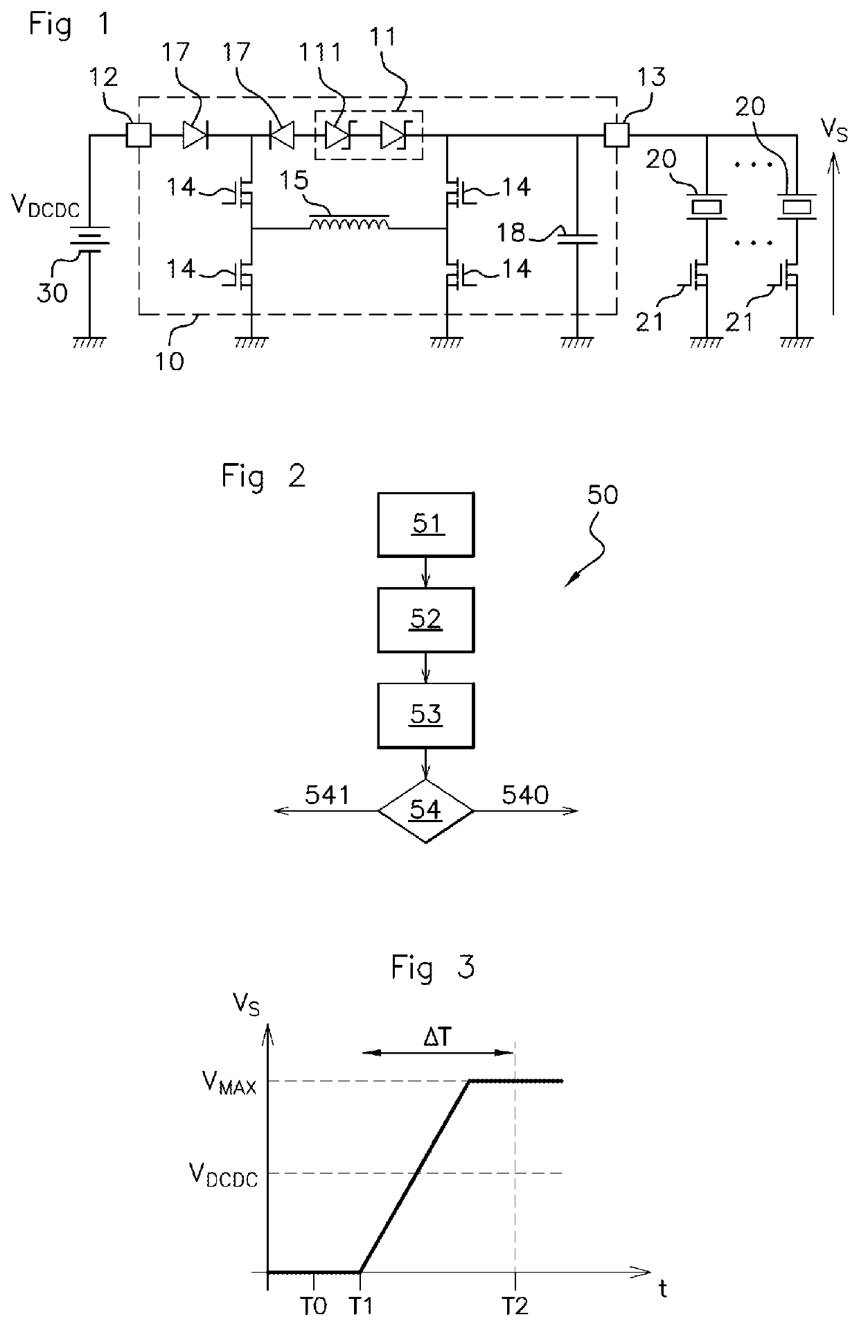
[0040]FIG. 1 schematically shows one exemplary embodiment of a control system for controlling piezoelectric injectors 20. In the example illustrated by FIG. 1, the same control system is used to electrically control several piezoelectric injectors 20. It should however be noted that the invention is applicable e...


PUM


Abstract

Disclosed is a method for detecting a malfunction of a voltage-limiting circuit of a control circuit, the control circuit including an output port connected to a capacitive actuator of a motor vehicle, an output voltage on the output port being, in the absence of a malfunction of the voltage-limiting circuit, equal to or lower than a theoretical maximum value. The capacitive actuator is arranged in series with a commutator, the method including steps of: placing the commutator in an open state; activating the control circuit; measuring the output voltage over the output port; and evaluating a criterion for detecting a malfunction of the voltage-limiting circuit as a function of the output voltage.

Description

CROSS-REFERENCE TO RELATED APPLICATIONS[0001]This application is the U.S. national phase of International Application No. PCT / EP2019 / 065192 filed Jun. 11, 2019 which designated the U.S. and claims priority to FR 1855069 filed Jun. 11, 2018, the entire contents of each of which are hereby incorporated by reference.BACKGROUND OF THE INVENTIONField of the Invention[0002]The present invention belongs to the field of motor vehicles, and relates more particularly to a method for detecting a malfunction in a control system for controlling a capacitive actuator, such as a piezoelectric injector of a motor vehicle engine.Description of the Related Art[0003]Nowadays, in motor vehicles, it is known practice to electrically control piezoelectric injectors by means of a control system notably including a control circuit, which is controlled by the engine computer of the motor vehicle.[0004]Conventionally, the control circuit includes an input port connected to an electrical power source, and an ...

Claims


Application Information

Patent Timeline
Patent Type & Authority Patents(United States)
IPC IPC(8): F02D41/20G01R31/52G01R31/00
CPCF02D41/2096G01R31/007G01R31/52F02D2041/2068F02D2041/2089F02D2041/2093G01R31/016
Inventor CHIABO, SÉBASTIENDELEPOUVE, SÉBASTIEN
Owner VITESCO TECH GERMANY GMBH
Why Eureka
Try Eureka