POS terminal

a terminal and terminal technology, applied in the field of terminals, can solve problems such as confusion for consumers, easy errors in verification in such a system, and frustration in scanning process for customers

Active Publication Date: 2022-05-10
EVERSEEN
View PDF7 Cites 0 Cited by
  • Summary
  • Abstract
  • Description
  • Claims
  • Application Information

AI Technical Summary

Benefits of technology

[0013]The POS terminal in accordance with the present invention provides improved feedback for the customer and the retail operator. In addition to the bar code scanning a plurality of illumination units arranged along the scanning path facilitate guiding the user through the self checkout process and the plurality of sensors detect additional information such as volume, shape, distance, and parameters relating to the customer to ensure a more reliable self-checkout process than has previously been possible. The use of the illumination units in a controlled manner through feedback from the control parameters generated in response to event data from the sensors ensures a stable active background which further ensures accuracy of the scanning process.
[0019]Generating a user alert may comprise selecting an illuminating unit of the plurality of illuminating units based on the control parameter and wherein communicating the user alert may comprise illuminating the selected illuminating unit. The controlled illumination units provide a stable background and also a controlled user guidance system.

Problems solved by technology

Several solutions have been proposed for an effective self-checkout system, however, many of these lead to confusion for the consumer.
Complex scenarios include loss prevention due to shop lifting, irregularities in scanning, intentional shop lifting, fraud and disguising thereof, multiple people in the POS terminal area or unexpected and ambiguous client actions.
However, the verification in such a system is prone to errors.
In addition, the scanning process can be frustrating for customers who need to repeatedly swipe the products from the pick up to drop off areas to ensure a correct scan.
However, there is still a level of frustration for the end customer.
Furthermore for the retailer the validation with these systems remains flawed and relies on the observance of a check out supervisor or a camera system.

Method used


Image

  • POS terminal
  • POS terminal
  • POS terminal

Examples


Embodiment Construction

[0055]The aspects of the technology mentioned above, as well as additional aspects, will now be described in greater detail. The aspects may be used individually, all together or in any combination of two or more, as the technology is not limited in this respect.

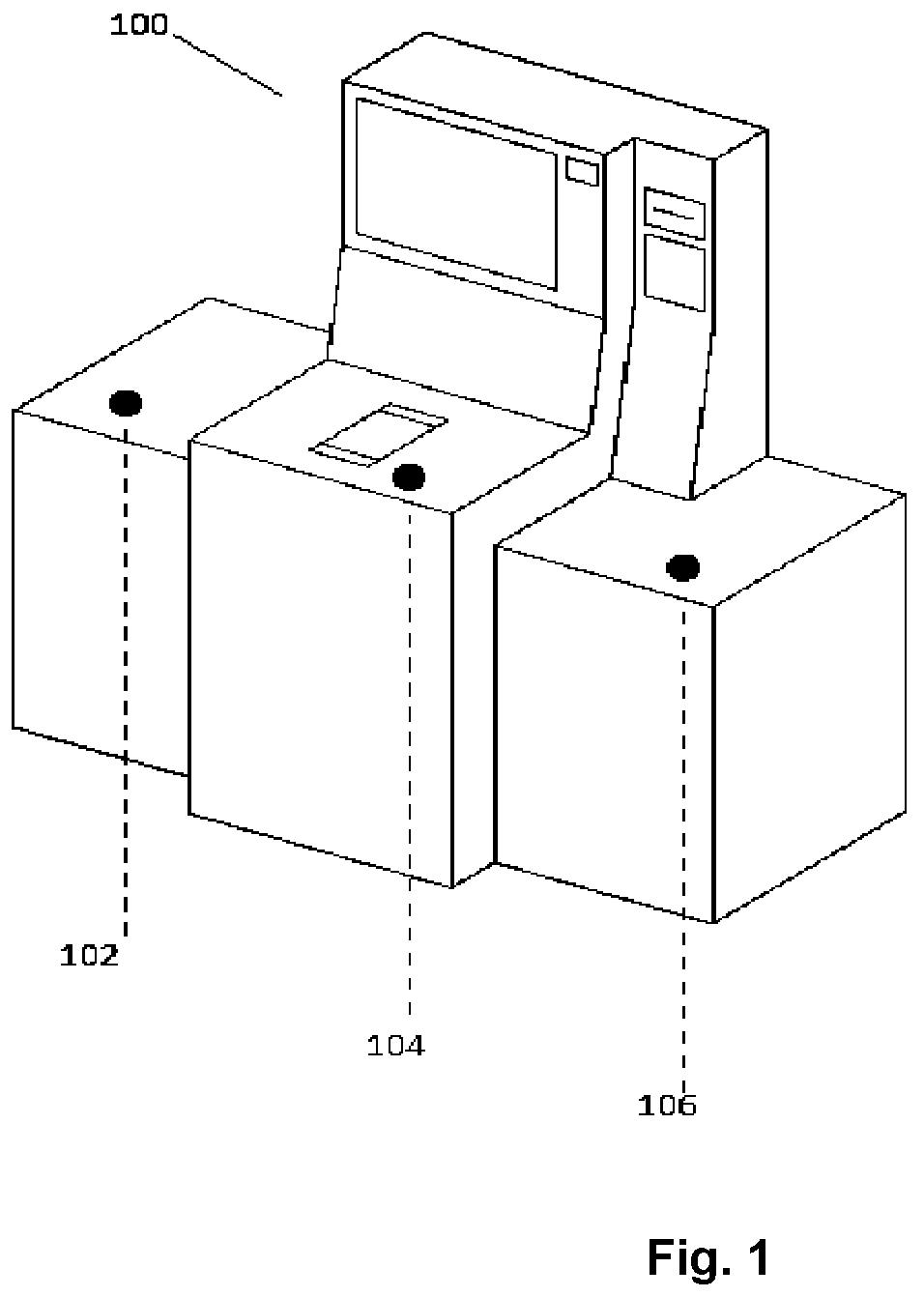
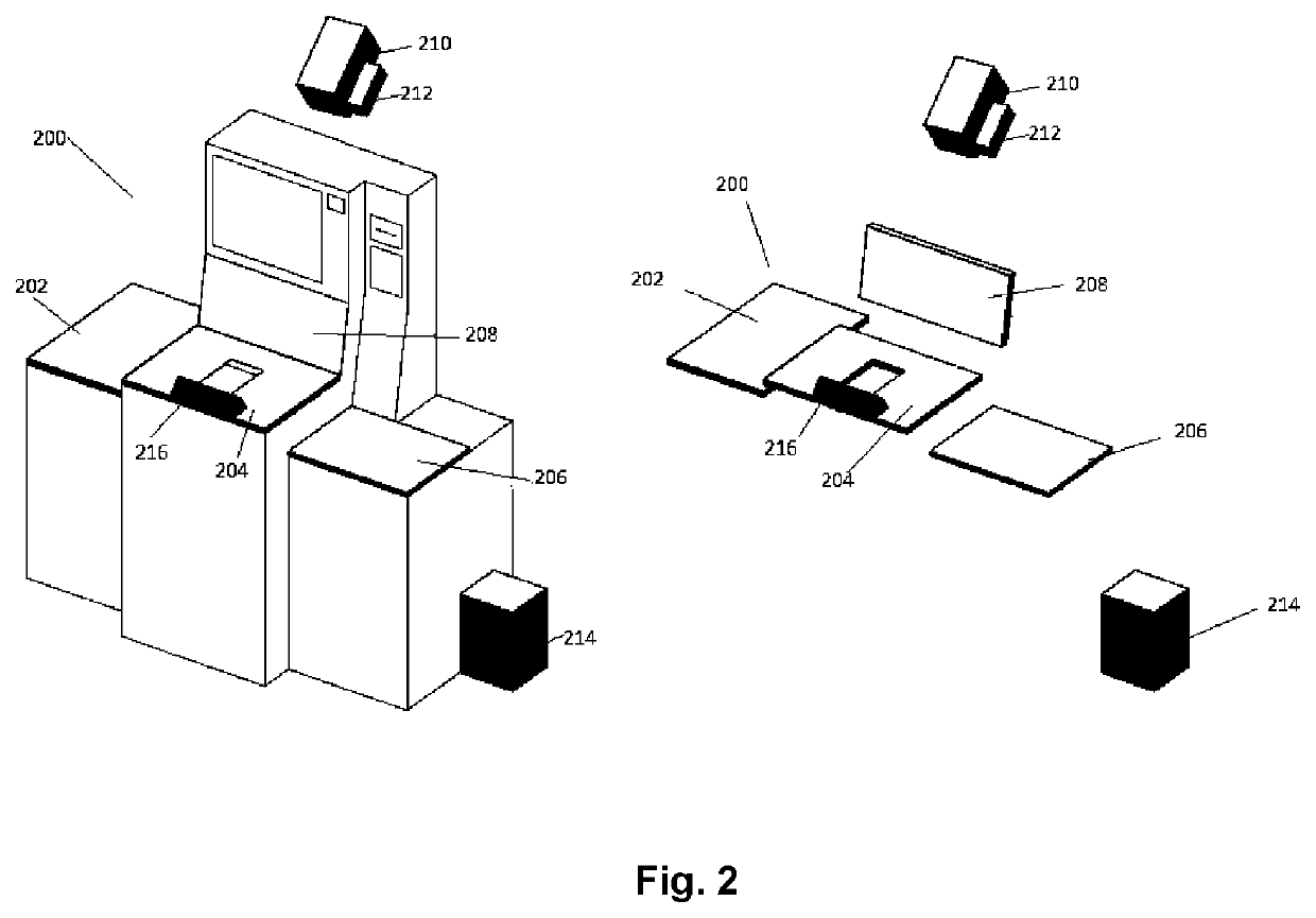
[0056]As shown in the exemplary embodiment of FIG. 2, the self-checkout or point of sale, POS terminal 200 of the present system includes a data acquisition device 200 for a POS terminal which in use generates event data as an output of a user implemented product scan. A scanning path is defined from an entry point, which may be an object pick up area, 202 for example to an exit point, which may be for example, an object drop off area 206. It will be appreciated that whilst in FIG. 2 the scanning path goes from the left hand side of the POS terminal to the right hand side, the scanning path may equally be in the opposite direction, i.e. from right to left.

[0057]The terminal of FIG. 2 also comprises a processing unit 214 whic...


PUM


Abstract

A POS terminal for a retail environment, comprising a data acquisition device for generating event data from a user scan of a product along a scanning path of the POS terminal, said path comprising an entry point and an exit point; and a processing unit for receiving at least a portion of event data from the data acquisition device and process the event data according to a set of predefined rules, to determine a control parameter for the POS terminal, generate a user alert based on the control parameter and communicate the user alert to the end user; the data acquisition device comprising: a universal product code, U PC, scanner; a plurality of illumination units arranged along the scanning path for illuminating the product; a plurality of sensors for sensing event data including a shape, size and volume of the product and a parameter of a hand of the user as the product is scanned along the scanning path.

Description

CROSS-REFERENCE TO RELATED APPLICATION[0001]The present application is a United States nationalization under 35 U.S.C. § 371 of International Patent Application No. PCT / EP2016 / 057664, filed Apr. 6, 2016, which claims priority to Great Britain Patent Application 1506494.2, filed Apr. 16, 2015, which is incorporated herein by reference for all purposes.TECHNICAL FIELD[0002]The present invention relates to a POS terminal and in particular a complementary flow regularisation system for a POS terminal in a self-checkout retail environments.BACKGROUND ART[0003]The development of self-checkout Point of Sale systems, whether cash, or cashless, has led to a significant increase in the efficiency of the purchasing process in a retail environment for the retail consumer. Several solutions have been proposed for an effective self-checkout system, however, many of these lead to confusion for the consumer. To mitigate this confusion guidance systems have been developed. The aim of these guidance ...

Claims


Application Information

Patent Timeline
Patent Type & Authority Patents(United States)
IPC IPC(8): G06Q20/20G08B7/06G07G1/01G07G1/00G06T7/62G08B5/36G08B21/18
CPCG06Q20/208G06Q20/209G06T7/62G07G1/0063G07G1/0072G07G1/01G08B5/36G08B7/066G08B21/182G06T2207/30232G07G3/006
Inventor O'HERLIHY, ALANCIUBOTARU, BOGDANCIOARGA, RAZVANPESCARU, DANVASILE, GUIPARVU, OVIDIUDAVID, CIPRIAN PETRUSACRIERU, CONSTANTIN PETRUGLAVAN, COSMIN CERNAZANUDOYLE, GAVIN
Owner EVERSEEN
Why Eureka
Try Eureka