
Electroluminescence display device having a through-hole in display area

a technology of display device and throughhole, which is applied in the direction of semiconductor devices, diodes, electrical apparatus, etc., can solve the problems of water and oxygen damage to the display device, and achieve the effect of maximizing the area of the display area

Active Publication Date: 2022-05-17
LG DISPLAY CO LTD
View PDF2 Cites 0 Cited by
  • Summary
  • Abstract
  • Description
  • Claims
  • Application Information

AI Technical Summary

Benefits of technology

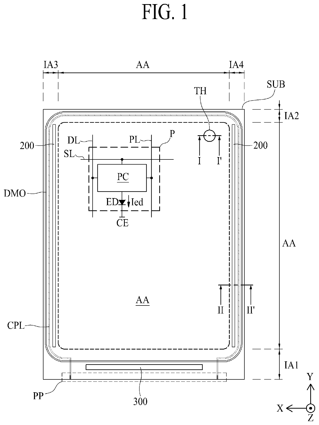
[0006]An object of the present disclosure is to provide an electroluminescence display device that maximizes an area of a display area, in which an additional device, such as a camera hole, for receiving light by passing through a substrate is arranged, or a through-hole for providing components by passing through a substrate is arranged in the display area for displaying an image. Another object of the present disclosure is to provide an electroluminescence display device having a structure that can shield water permeation from a light emitting diode of a display element arranged near a through-hole even though the through-hole is provided in a display area.
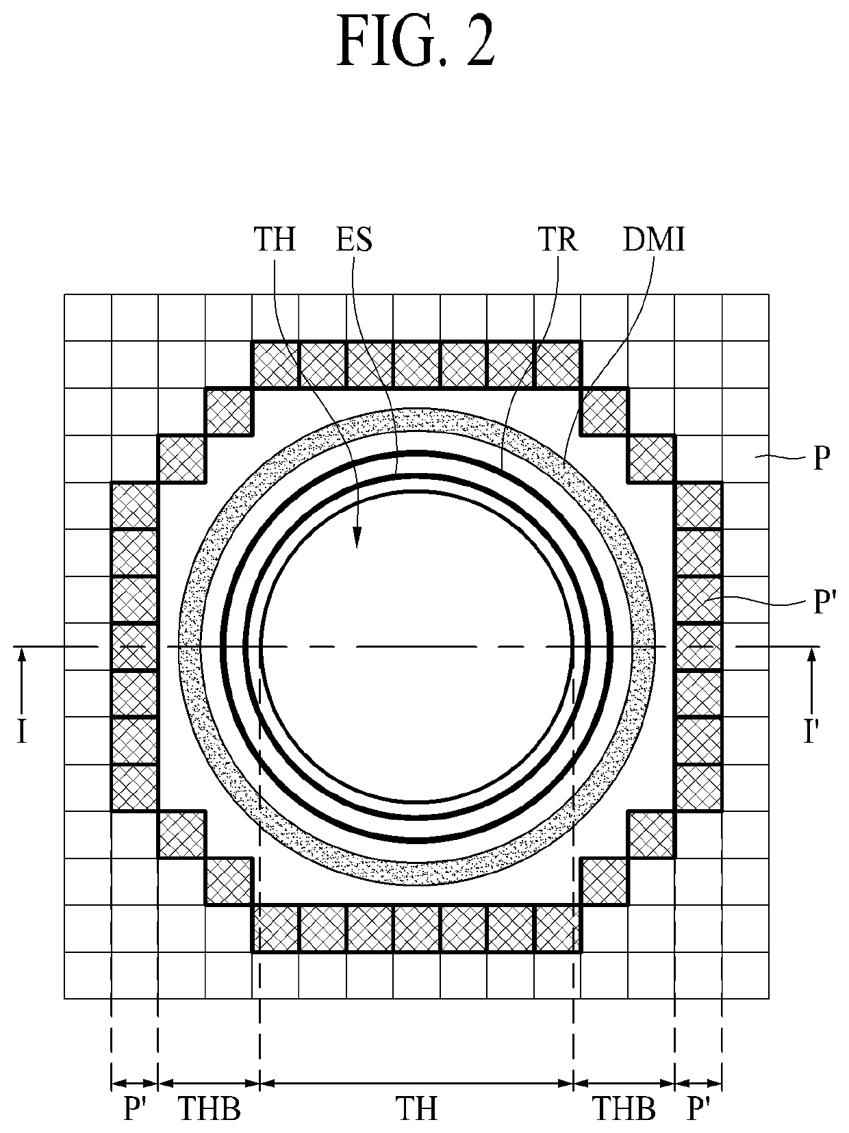
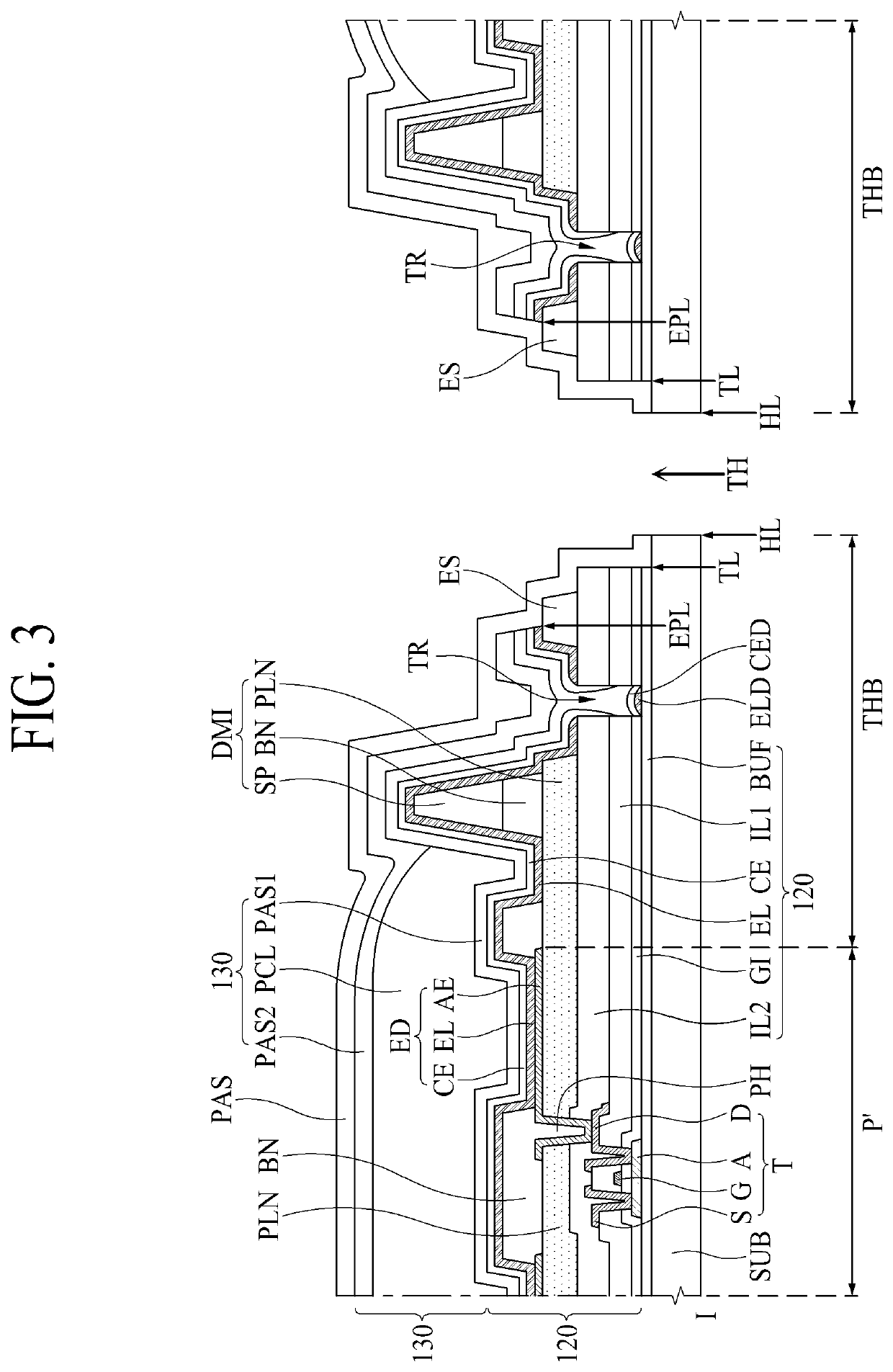
[0030]In the electroluminescence display device according to the present disclosure, since the through-hole is provided in the display area, an area ratio occupied by the non-display area is minimized, and an area ratio of the display area is maximized. In the electroluminescence display device according to the present disclosure, since the trench is provide near the through-hole, continuity of the light emitting layer is partially disconnected, whereby water is prevented from permeating into the light emitting diode. Also, an upper passivation film covering a section of thin films etched in a portion of the through-hole is further provided, whereby water or oxygen is prevented from permeating into a pixel area. Moreover, exposed sections of the thin films deposited in the portion of the through-hole are not arranged on the same vertical surface but arranged on a plurality of vertical surfaces spaced apart from one another at a certain distance, whereby a structure for enhancing an encapsulation power and an adhesive power of the upper passivation film is provided. In the electroluminescence display device according to the present disclosure, since a hole passing through the display panel is provided in the display area, applicability of the display device is high, and the display device can be applied to various products. In the electroluminescence display device according to the present disclosure, even though the hole passing through the display panel is formed in the display area, external water and particles are shielded from permeating and being diffused into the display element, whereby it is possible to make sure of stability and lifetime of the product.

Problems solved by technology

However, the electroluminescence display device has a drawback in that it is vulnerable to water and oxygen.

Method used


Image

  • Electroluminescence display device having a through-hole in display area
  • Electroluminescence display device having a through-hole in display area
  • Electroluminescence display device having a through-hole in display area

Examples


first embodiment

[0083]Hereinafter, a sectional structure of the electroluminescence display device comprising a through-hole in a display area according to the first embodiment of the present disclosure will be described with reference to FIGS. 3 to 5. FIG. 3 is a cross-sectional view taken along line I-I′ of FIG. 1, illustrating a structure of a portion where a through-hole is arranged in the electroluminescence display device according to the first embodiment of the present disclosure. FIG. 4 is a cross-sectional view taken along line II-II′ of FIG. 1, illustrating a structure of a boundary portion of a display area and a non-display area in the electroluminescence display device according to the first embodiment of the present disclosure.

[0084]Referring to FIGS. 3 and 4, the electroluminescence display device according to the first embodiment of the present disclosure can include a substrate SUB, a buffer film BUF, a pixel array layer 120, a spacer SP, an inner dam DMI, an outer dam DMO, an enca...

second embodiment

[0142]Hereinafter, the electroluminescence display device according to the second embodiment of the present disclosure will be described with reference to FIG. 6. FIG. 6 is a cross-sectional view taken along line I-I′ of FIG. 1, illustrating a structure of a portion where a through-hole is arranged in an electroluminescence display device according to the second embodiment of the present disclosure.

[0143]Referring to FIG. 6, the electroluminescence display device according to the second embodiment of the present disclosure has an almost same structure as that of the first embodiment except a structure between the etch-stopper ES and the through-hole TH. Therefore, a description of the same elements will be omitted or a description will be given based on main parts. Also, since a structure of a portion where an outer dam DMO is formed is the same as that of the first embodiment, it can easily be understood with reference to the first embodiment based on FIG. 4 even without a separate...

third embodiment

[0155]Hereinafter, the electroluminescence display device according to the third embodiment of the present disclosure will be described with reference to FIG. 7. FIG. 7 is a cross-sectional view taken along line I-I′ of FIG. 1, illustrating a structure of a portion where a through-hole is arranged in an electroluminescence display device according to the third embodiment of the present disclosure. In a structure of the electroluminescence display device according to the third embodiment of the present disclosure, most of elements are the same as those of the first and second embodiments except a structure between the trench TR and the through-hole TH. Therefore, a description will be given based on a different portion.

[0156]Referring to FIG. 7, an end HL of the through-hole TH means a rim that determines a shape of the through-hole TH. An end TL of a thin film layer is arranged between the end HL of the through-hole TH and the trench TR. In this case, the thin film layer is comprise...


PUM

PropertyMeasurementUnit
thicknessaaaaaaaaaa
electroluminescenceaaaaaaaaaa
areaaaaaaaaaaa

Abstract

An electroluminescence display device comprising a through-hole in a display area is discussed. The electroluminescence display device according to one embodiment of the present disclosure comprises a substrate having a display area and a non-display area arranged near the display area; a light emitting diode in the display area; an encapsulation layer on the light emitting diode; a through-hole arranged inside the display area to penetrate the substrate; an inner dam surrounding the through-hole; a trench arranged between the inner dam and the through-hole; and an etch-stopper arranged between the trench and the through-hole on the an insulating layer.

Description

CROSS-REFERENCE TO RELATED APPLICATIONS[0001]This application claims the priority benefit of the Korean Patent Application No. 10-2018-0173299 filed on Dec. 31, 2018, which is hereby incorporated by reference as if fully set forth herein.BACKGROUNDField of the Invention[0002]The present disclosure relates to an electroluminescence display device having a through-hole in a display area, and more particularly, to an electroluminescence display device provided with a device, such as a camera hole, for receiving light by passing through a substrate or a through-hole, into which an additional device passing through a substrate can be inserted, arranged in a display area.Discussion of the Related Art[0003]Among display devices, an electroluminescence display device is a self-light emitting device, and has advantages in that a viewing angle and a contrast ratio are more excellent than those of other display devices. Further, since the electroluminescence display device does not require a s...

Claims


Application Information

Patent Timeline
Patent Type & Authority Patents(United States)
IPC IPC(8): H01L27/32H01L33/24H01L51/52H01L25/075H01L33/56
CPCH01L27/3234H01L25/0753H01L27/326H01L33/24H01L33/56H01L51/5253
Inventor HUH, HAERI
Owner LG DISPLAY CO LTD
Learn More