Power supply device
a power supply device and power supply technology, applied in the direction of emergency power supply arrangements, transportation and packaging, dc source parallel operation, etc., can solve the problems of increased energy loss, reduced profit obtainable by operating the power storage device according to different energy prices, and low power conversion efficiency, so as to minimize the effect of energy conversion loss
- Summary
- Abstract
- Description
- Claims
- Application Information
AI Technical Summary
Benefits of technology
Problems solved by technology
Method used
Image
Examples
first embodiment
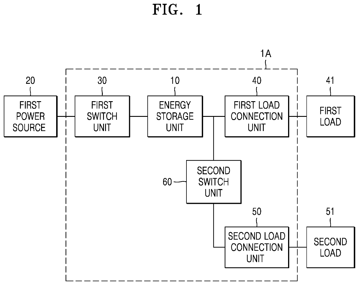
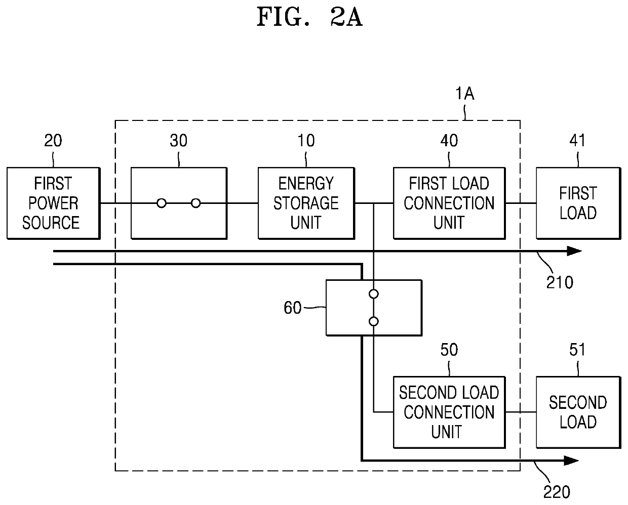
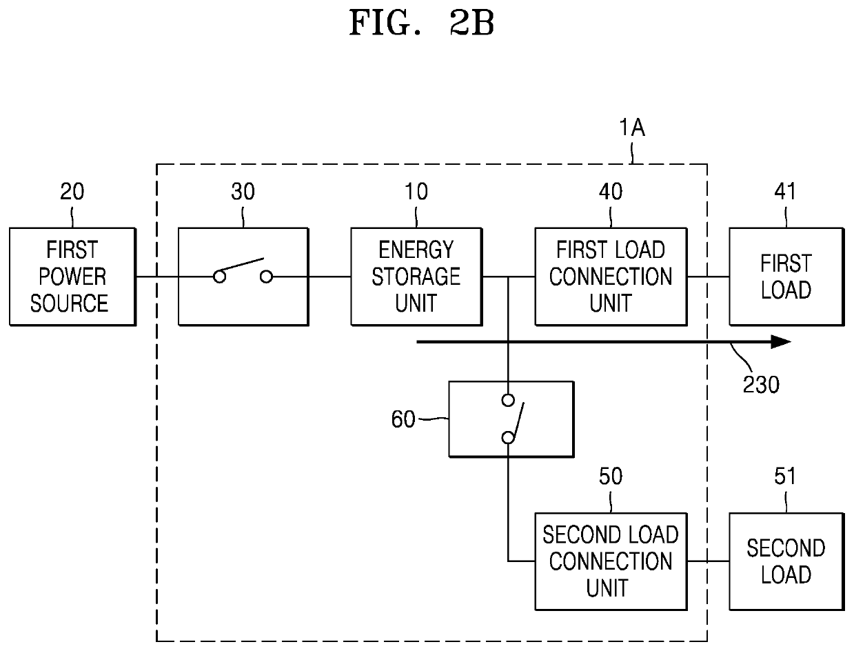
[0042]FIG. 1 illustrates a schematic configuration of a power supply device 1A according to a first embodiment of the present disclosure.
[0043]Referring to FIG. 1, the power supply device 1A according to the first embodiment of the present disclosure may include an energy storage unit 10, a first switch unit 30, a first load connection unit 40, a second load connection unit 50, and a second switch unit 60.
[0044]The energy storage unit 10 according to the present embodiment may be any unit capable of storing electrical energy. For example, the energy storage unit 10 may be any one or a combination of one or more of an uninterruptible power supply (UPS), an energy storage system (ESS), and an uninterruptible energy storage (UES). However, this is an example, and the idea of the present disclosure is not limited thereto. That is, any unit capable of receiving electrical energy and storing the electrical energy temporarily and / or permanently may be used as the energy storage unit 10 of ...
second embodiment
[0067]FIG. 3 illustrates a schematic configuration of a power supply device 1B according to a second embodiment of the present disclosure.
[0068]Referring to FIG. 3, the power supply device 1B according to the second embodiment of the present disclosure may further include a second power source 70 and a third switch unit 80 in addition to the energy storage unit 10, the first switch unit 30, the first load connection unit 40, the second load connection unit 50, and the second switch unit 60 that are included in the power supply device 1A (refer to FIG. 1) of the first embodiment.
[0069]Since the energy storage unit 10, the first switch unit 30, the first load connection unit 40, the second load connection unit 50, and the second switch unit 60 have been described in detail in the first embodiment, detailed descriptions thereof will be not be presented here.
[0070]According to the present embodiment, the second power source 70 may refer to any energy providing unit capable of supplying ...
third embodiment
[0083]FIG. 5 illustrates a schematic configuration of a power supply device 1C according to a third embodiment of the present disclosure.
[0084]Referring to FIG. 5, the power supply device 1C according to the third embodiment of the present disclosure may further include a control unit 100 in addition to the energy storage unit 10, the first switch unit 30, the first load connection unit 40, the second load connection unit 50, and the second switch unit 60 that are included in the power supply device 1A (refer to FIG. 1) of the first embodiment.
[0085]The control unit 100 of the present embodiment may include any kind of device such as a processor capable of processing data. Here, the “processor” may refer to a data processing device included in hardware and having a physically structured circuit to execute code of programs or functions expressed with instructions. Examples of the data processing device included in hardware may include a microprocessor, a central processing unit (CPU)...
PUM
 Abstract
Description
Claims
Application Information
 - R&D
- Intellectual Property
- Life Sciences
- Materials
- Tech Scout
- Unparalleled Data Quality
- Higher Quality Content
- 60% Fewer Hallucinations
Browse by: Latest US Patents, China's latest patents, Technical Efficacy Thesaurus, Application Domain, Technology Topic, Popular Technical Reports.
© 2025 PatSnap. All rights reserved.Legal|Privacy policy|Modern Slavery Act Transparency Statement|Sitemap|About US| Contact US: help@patsnap.com


