Method for fluid measurement for a discrete area of a fluid supply network

a fluid supply network and discrete area technology, applied in the field of discrete area fluid flow measurement, can solve the problems of leakage in the pipeline network, the consequences of leakage can be very destructive, and one often faces the task of leakage detection and leakage localization, so as to achieve fluid easy and convenient

Active Publication Date: 2022-05-24
SIEMENS AG
View PDF11 Cites 1 Cited by
  • Summary
  • Abstract
  • Description
  • Claims
  • Application Information

AI Technical Summary

Benefits of technology

[0025]In view of the foregoing, it is an object of the invention to provide a method for easily and conveniently achieving fluid flow measurement in a discrete area, especially for the district metered areas, of the fluid supply network.
[0039]This approach can be easily extended for more than two distribution pipes.
[0044]The above Eq. 1 of the fluid flow Qi allows the calculation of the fluid flow Qi in the main pipe through the boundary of the discrete area without having a costly flow meter installed on the main pipe.
[0049]The above criteria of selection of the key metering points for the further measurement makes the calculation of the fluid flow in and / or out of the discrete area more accurate and precise.
[0056]In a possible embodiment of the method, the selected key metering point equipped with the pressure sensor and the consumption gauge can have the pressure sensor and the consumption gauge located in different places on the distribution pipe, such that the consumption gauge is located downstream the pressure sensor. This feature allows more flexibility in equipment installation in the fluid supply network.
[0058]This feature allows the use of an already existing system of consumption gauges without additional installations and optimizing the number of the pressure sensors to be installed.

Problems solved by technology

The leaks in the pipeline network can be caused by various reasons, e.g., damage from nearby excavation equipment, corrosion of pipes, accidents or earth movement.
When monitoring hydraulic supply networks, one often faces the task of leakage detection and leakage localization.
Consequences of the leakage can be very destructive.
However, sometimes considerable water losses occur in water supply networks.
These losses put a strain on water supply and inflate the management cost for the water utilities because they represent water that is extracted and treated but never reaches the consumers.
In many cases, minor water leakages deriving from the inefficient hydraulic seal of junctions or from small cracks on pipes may lie hidden for a long time, sometimes for months or even years.
Major leakages can be easily observed when significant damages to the pipes occur, because they usually result in large amounts of water erupting from ground or flowing in the consumer properties.
The prior art DMA's approach, however, has its disadvantages.
Firstly, dividing the water supply network into smaller areas comes with a cost—the cost of an area survey, installation design, flow meter and chamber installation etc., is substantial, particularly if small areas (e.g., less than 1000 consumers) are chosen.
Consequently, flow meters and valves to be installed on this main pipes are big and therefore also expensive.
Moreover, creating DMAs by traditional ways requires the ‘permanent’ closure of many boundary valves—and, because of area supply arrangements and network characteristics (such as topography and low system pressures) some networks are hydraulically difficult to divide into single-feed DMAs without disadvantaging consumers.
However the measurement of inflow into the DMA and outflow from the DMA is not an easy task.
In general, the existing ways of measuring fluid flow into and out of a discrete area, e.g., a district metered area, of a supply network require very sophisticated and expensive flow meters, the installation of which is complex, costly and time consuming.

Method used


Image

  • Method for fluid measurement for a discrete area of a fluid supply network
  • Method for fluid measurement for a discrete area of a fluid supply network
  • Method for fluid measurement for a discrete area of a fluid supply network

Examples


Embodiment Construction

[0069]Various embodiments are described with reference to the drawings, where like reference numerals are used to refer to like elements throughout. In the following description, for purposes of explanation, numerous specific details are set forth in order to provide a thorough understanding of one or more embodiments. It may be evident that such embodiments may be practiced without these specific details.

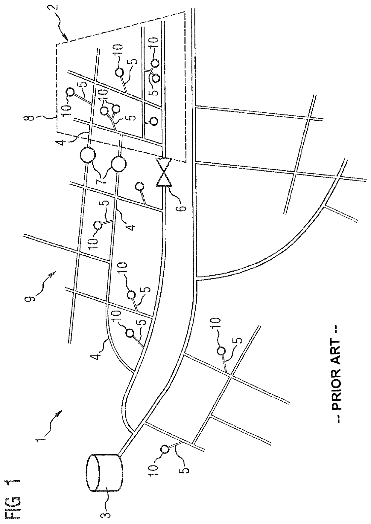
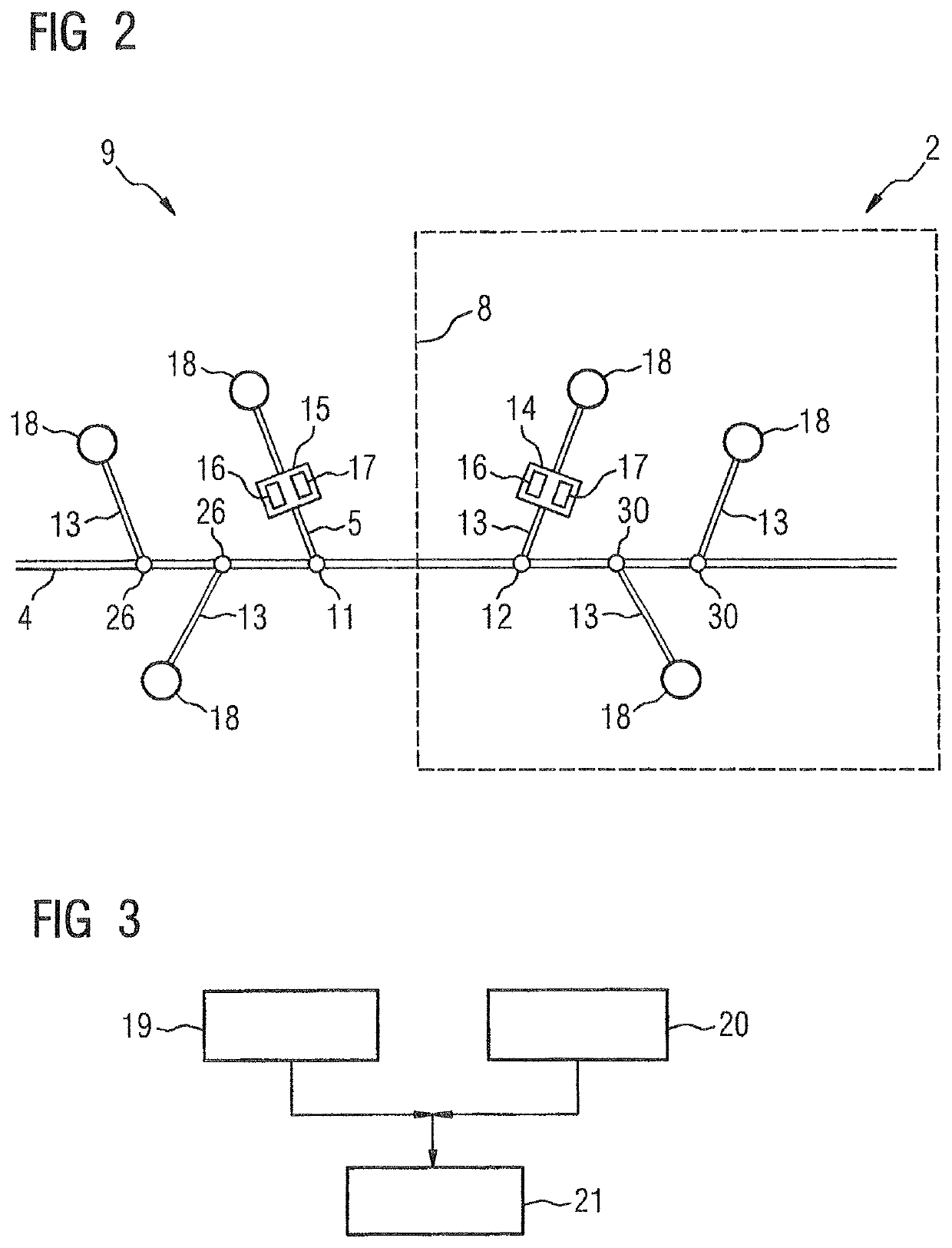
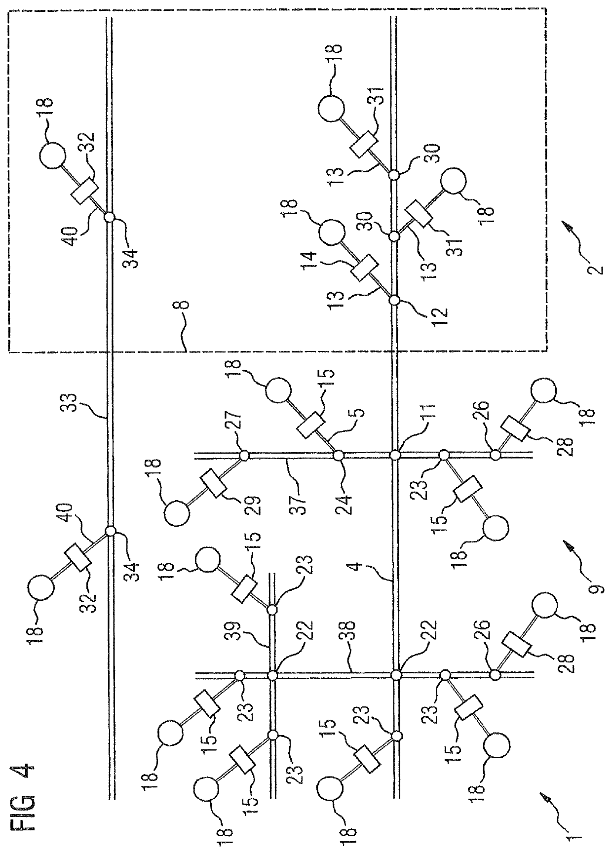
[0070]The invention relates to a system 36 for fluid flow measurement for a discrete area 2 of a fluid supply network 1.

[0071]FIG. 2 shows a block diagram of a part of the fluid supply network 1 with the discrete area 2 isolated in accordance with the present invention and illustrates the insight of what the invention is based on. The main pipe 4 of the fluid supply network 1 crosses the boundary 8 of the discrete area 2 of the fluid supply network 1, where the boundary 8 separates the discrete area 2 and a further area 9 of the fluid supply network 1. Distribution pipes 13 of the ...


PUM


Abstract

A method for fluid flow measurement for a discrete area of a fluid supply network, where the fluid supply network includes a network of pipes that includes a main pipe for transporting fluid from a source into the fluid supply network for delivery to consumers, wherein the main pipe crosses a boundary between the discrete area and a further area of the fluid supply network, which is outside of the discrete area, and a plurality of distribution pipes each transport fluid from the main pipe to a consumer, where fluid pressure and the fluid consumption on at least two selected key metering points located inside and outside of the discrete area are measured, and where the fluid pressure and the fluid consumption measured on these selected key metering points the fluid flow in the main pipe that crosses the boundary of the discrete area is calculated.

Description

CROSS-REFERENCE TO RELATED APPLICATIONS[0001]This is a U.S. national stage of application No. PCT / RU2016 / 000370 filed Jun. 20, 2016.BACKGROUND OF THE INVENTION1. Field of the Invention[0002]The present invention relates to a method for fluid flow measurement for discrete areas inside a fluid supply network.2. Description of the Related Art[0003]Pipeline networks are the most economic and safest mode of transportation for fluids like water, oil, gases and other fluid products. As a way to provide long-distance transport, pipelines have to fulfill high demands of safety, reliability and efficiency. If properly maintained, pipelines can last indefinitely without leaks. The leaks in the pipeline network can be caused by various reasons, e.g., damage from nearby excavation equipment, corrosion of pipes, accidents or earth movement.[0004]Such a system of interconnected pipes that carries a pressurized fluid, such as water, oil, gases and other fluid products, is called hydraulic supply ne...

Claims


Application Information

Patent Timeline
Patent Type & Authority Patents(United States)
IPC IPC(8): G01M3/28G01F15/00G01F15/075
CPCG01M3/28G01F15/005G01F15/0755G01M3/2815G01F1/66
Inventor KARNACHEV, ALEXEY ALEXANDROVICHMANGUTOV, OLEG VLADIMIROVICHMOKHOV, ILYA IGOREVICHKOZIONOV, ALEXEY PETROVICHVENIAMINOV, NICOLAY ANDREEVICH
Owner SIEMENS AG
Why Eureka
Try Eureka