Touch sensor-antenna module and display device including the same

a technology of touch sensor and display device, which is applied in the direction of resonant antenna, particular array feeding system, instruments, etc., can solve the problems of disturbance of the impedance property of receiving a desired frequency, the antenna may not obtain the desired gain property, etc., to improve the radiation reliability of the antenna pattern, improve the directivity of the antenna and the antenna gain, and prevent the effect of signal disturbance and impedance mismatching by the trace of the touch sensor

Active Publication Date: 2022-05-24
DONGWOO FINE CHEM CO LTD +1
View PDF14 Cites 1 Cited by
  • Summary
  • Abstract
  • Description
  • Claims
  • Application Information

AI Technical Summary

Benefits of technology

[0007]According to an aspect of the present invention, there is provided a touch sensor-antenna module having improved signaling efficiency and reliability.
[0008]According to an aspect of the present invention, there is provided a display device including a touch sensor-antenna module with improved signaling efficiency and reliability.
[0025]According to exemplary embodiments of the present invention, a touch sensor-antenna module may include a plurality of antenna patterns as an array so that radiation directivity and antenna gain may be improved.
[0026]The antenna patterns may be disposed over or under a touch sensor such that a transmission line included in the antenna pattern may not overlap a trace included in the touch sensor. Thus, signal disturbance and impedance mismatching by the trace of the touch sensor may be prevented and radiation reliability of the antenna patterns may be improved.
[0027]In some embodiments, a feeding may be selectively performed to only an antenna pattern that may not overlap the trace of the plurality of the antenna patterns via an integrated circuit (IC) chip so that signaling / radiation reliability may be enhanced.

Problems solved by technology

When the antenna and the touch sensor are present in one display device, desired gain property of the antenna may not be obtained due to a mutual signal interference and an impedance property for receiving a desired frequency may be disturbed.

Method used


Image

  • Touch sensor-antenna module and display device including the same
  • Touch sensor-antenna module and display device including the same
  • Touch sensor-antenna module and display device including the same

Examples


Embodiment Construction

[0036]According to exemplary embodiments of the present invention, a touch sensor-antenna module that includes a touch sensor electrode layer including a plurality of sensing electrodes and traces electrically connected to the sensing electrodes, and an antenna electrode layer including an antenna pattern is provided. Further, a display device having improved signaling reliability and efficiency from the touch sensor-antenna module is also provided.

[0037]Hereinafter, the present invention will be described in detail with reference to the accompanying drawings. However, those skilled in the art will appreciate that such embodiments described with reference to the accompanying drawings are provided to further understand the spirit of the present invention and do not limit subject matters to be protected as disclosed in the detailed description and appended claims.

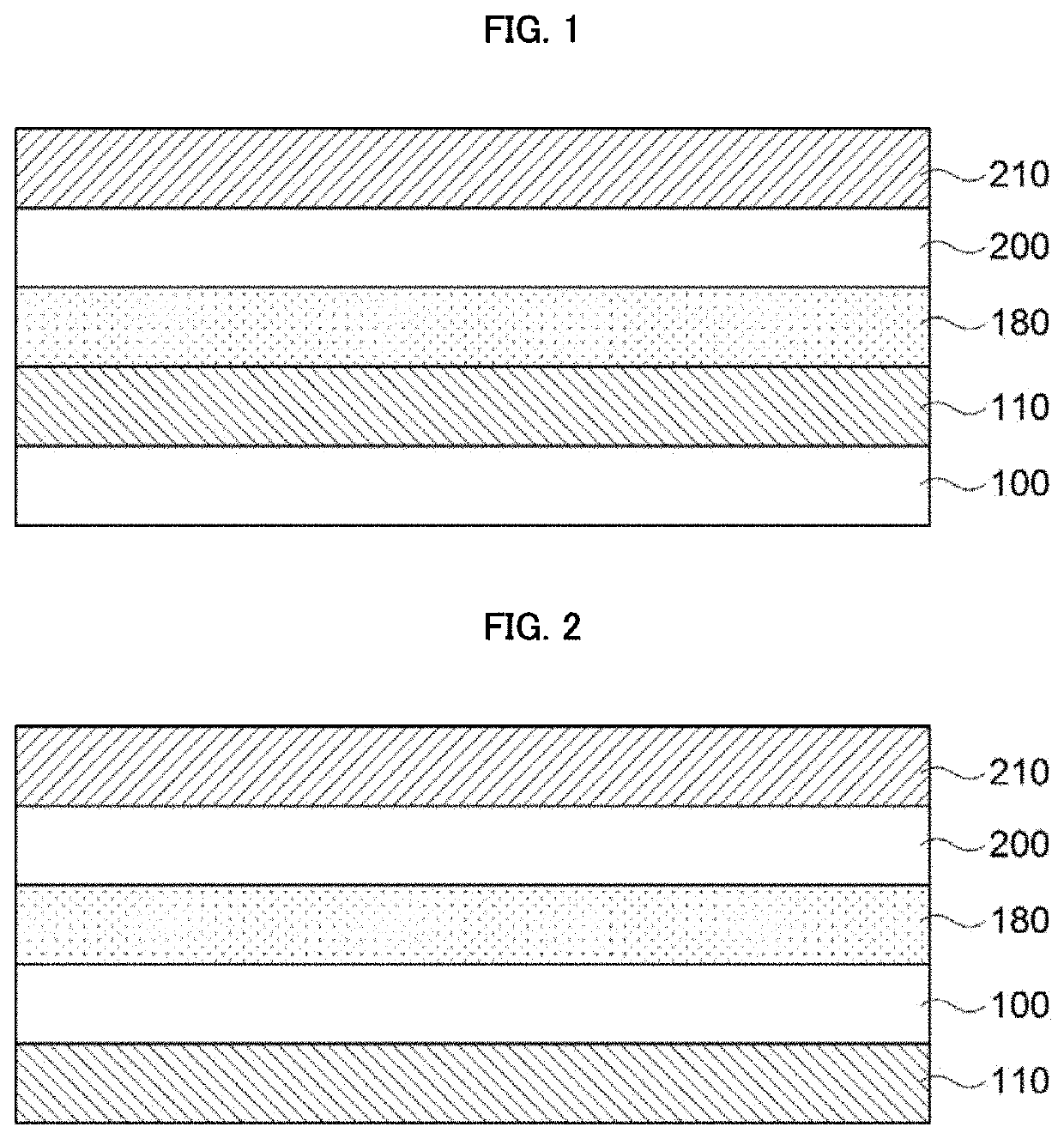
[0038]FIGS. 1 and 2 are cross-sectional views illustrating touch sensor-antenna modules in accordance with exemplary embodi...


PUM

PropertyMeasurementUnit
dielectric constantaaaaaaaaaa

Abstract

A touch sensor-antenna module includes a touch sensor electrode layer including a plurality of sensing electrodes and traces electrically connected to the sensing electrodes, and an antenna electrode layer disposed over the touch sensor electrode layer or under the touch sensor electrode layer. The antenna electrode layer includes an antenna pattern that does not overlap the traces in a planar view. An electrical interference from the traces may be reduced to improve an antenna signal property.

Description

CROSS REFERENCE TO RELATED APPLICATIONS AND CLAIM OF PRIORITY[0001]The present application is a continuation application to International Application No. PCT / KR2019 / 012249 with an International Filing Date of Sep. 20, 2019, which claims the benefit of Korean Patent Application No. 10-2018-0118469 filed on Oct. 4, 2018 at the Korean Intellectual Property Office, the disclosures of which are incorporated by reference herein in their entirety.BACKGROUND1. Field[0002]The present invention relates to a touch sensor-antenna module and a display device including the same. More particularly, the present invention related to a touch sensor-antenna module including an antenna pattern and a touch sensor layer, and a display device including the same.2. Description of the Related Art[0003]As information technologies have been developed, a wireless communication technology such as Wi-Fi, Bluetooth, etc., is combined with a display device in, e.g., a smartphone. In this case, an antenna may be co...

Claims


Application Information

Patent Timeline
Patent Type & Authority Patents(United States)
IPC IPC(8): G06F3/041G06F3/047H01Q1/24G06F3/044
CPCG06F3/0412G06F3/047G06F3/0443G06F3/0446H01Q1/243G06F2203/04103G06F3/041H01Q1/2258H01Q1/38H01Q1/50H01Q1/52H01Q21/0006H01Q1/44H01Q9/0407H01Q21/065H01Q1/2283G06F2203/04112
Inventor OH, YUN SEOKKIM, JONG MINRYU, HAN SUBHONG, WON BIN
Owner DONGWOO FINE CHEM CO LTD
Why Eureka
Try Eureka